
I’ve been fascinated with automatic chicken coop doors. My current auto coop door closer has been working like a champ for months. I received a lot of great replies to that thread, and one of them was from a visitor named Bob. I was so impressed with his design and pictures I asked him if I could post his comments and pictures as an article here. I’m SUPER glad he agreed. So, below are his words:
Here is the automatic door I built with an automatic car antenna (click the image to see it in action). I chose the antenna method because it has a built in stop when it reaches its end in both directions. This eliminates the need of more circuitry to control “run timeâ€.
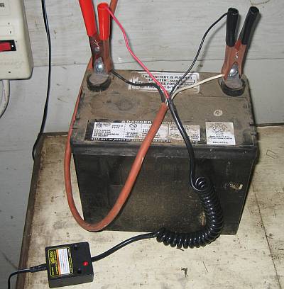
Mine runs off a little 12v lawn tractor battery. The battery is kept up to charge with a “float†charger. The door opens and closes with a photo light sensor. The reason for the battery is so that a power failure will not cause a problem. The reason for the light sensor is so that the length of daylight does not need to be constantly adjusted on a timer. BUT, you can simplify things and use an ordinary appliance timer plugged into an AC outlet, and then use a 12v DC power supply to power the antenna.
This is just one way to use an automatic car antenna. With some imagination you could probably come up with many more designs.
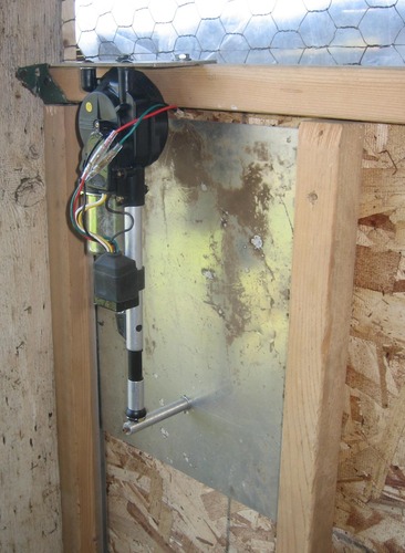
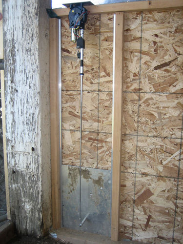
As you can see the antenna is mounted upside down. The door is made from an 1\8″ ALUMINUM panel. It is light in weight but very strong. The door channels are 1/4″. I have a 3″ spacer connected to the tip of the antenna to the door. You can measure the distance you need to determine the spacing length. I used a piece of aluminum stock and tapped each side to mount it. The side on the antenna tip has a hole for the tip to set in, and then I used the tapped hole as a “set screw†to keep the tip in place. I have my tip connected towards the bottom of the door. This makes the length of the door channel a bit shorter in order to match the up and down stroke of the antenna.
Be sure to carefully measure the lengths and travel distances needed for the antenna to move up and down freely. I have heard of some discussion that the travel distance does not need to be exact because the antenna’s “auto stop†feature will sense the end travel and the motor will time out. But that will be up to you.
If you do not have some aluminum sheeting lying around, you can find some at Lowe’s or etc. Aluminum can be easily cut with your skill saw. Just make sure you have a carbide blade and wear safety goggles. Even some type of plastic sheet would work. Just keep it light and strong.
The door channels can be purchased also at Lowe’s or Home Depot.
The best price for the antenna was on-line at Beachaudio.com, but they may be out of stock. Just search the web for the least expensive “automatic antennaâ€. Mine was about $35.00. The antenna MUST only have three wires. (Beware of the non automatic antennas that require the user to “toggle†the antenna up and down manually). Two wires connect directly to your power source. The other wire that is not black or red, is the “up down†trigger. That is the wire that you connect to the timer or sensor circuit.
If you go with the 12V battery, the float charger can be bought at Harbor Freight Tools for under $10.00.
I have updated this article to mention that the there may be a better control system other than the night/daylight sensor that is described below. I have used this sensor for about a year. However, just recently I noticed that the control unit was sometimes “confused†in the mornings and would make the antenna move up and down erratically. Not fun for the chickens. It was mainly due to setting the photocell too sensitive in order to stay open at night as long as possible. Please be sure to read the later posts regarding an Intermatic ST01C timer. This timer is very unique because it does not rely on household current to operate. It is also very unique because it has an “astronomical†feature which updates the internal clock when dusk and dawn occurs in your region. It is powered by a 2 year lithium battery. Below is the night/daylight photocell circuit, if you decide to want to experiment with it.
Here is the circuit. Its pretty simple and self explanatory and would require someone that has done a little soldering in the past.
The only thing that is really not explained is the CDS photocell. One could try different types to see which works best. The one I ended up using was from a photocell variety package purchased from Radio Shack.
If you decide to go with the photocell circuit, the antenna’s power wires (red and black) must be always connected to the 12vdc power source and not be controlled by the photocell circuit.
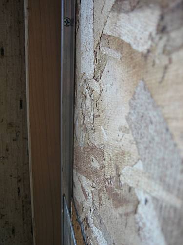
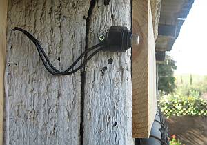
A few thumbnails you can click on for the control box, door channel, battery / charger, photocell
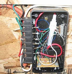
On the other side of the box I have a little slider switch that makes the door close manually.
The tip spacer/connector will probably be the hardest part for a lot of people to figure out to. There plenty of ways to get that done. I had a piece of an aluminum rod that was solid. I drilled and tapped each side of it. There is a screw going through the outside of the door to one side of the rod. I drilled a hole in the rod for the antenna tip to sit in. The screw on that side of the rod is a set screw that keeps the tip in place.
(Rob Note: A huge thanks to Bob for this great design, pics and wrtieup and for letting me post it on the site. I know we are both looking forward to reading some of your comments!)
Bob
In # 36 you explained that you can put the wires opposite voltage toghter so it will extend then retract at different times as needed, but my antenna wont do that and my 12V power sources work ok sometimes and not other times any sujestions
Hi Rodney,
First let’s let the readers know that you do not have an antenna with a trigger wire, but one that has only 2 wires that require a polarity reversal when needing to retract it. Like in post 36.
For your antenna, your power sources both need to be 12-15V DC at no less than 1 Amp (1000MA). The more the better. Unless your antenna is just a current hog:) If you have a volt meter to attach while the antenna moves, check for voltage drop. You should be able to connect one source up to the antenna one way, and connect the other source to the antenna the other way (cross polarity). Usually this should NEVER be done, but because you are only turning one source on, ONE AT A TIME, it should control the antenna up and down. I did not know if this would actually work, but I did a test on my bench with two power packs and it worked for me. If everything I mentioned is how you are doing it, then maybe there’s something different with your sources compared to mine. You would then need to go with a relay, which is not that difficult to do.
Keep me posted.
Bob
Bob,
Let me start over, The type of antenna is a automatic universal type, it has 2 wires, red and yellow, plus there is a switch wire that could be connected to both of these wires, I think which would be used for manual operation. which will not be needed. I took the to power wires and connected them to a 12v battery red + yellow – , the ant extended, I reversed the two wires, it retracted.
I then tested it using a 12v 3amp power supply and it extended and retracted, then I connected two power supplies in reverse on top of each other plugged in one for it to extend and it extened, un-plugged it and plugged in the one for retracting and it did not retract, I had to use the 12v battery again to make it retract, why is this?
I should be-able to piggyback the wires in reverse since you are using two different power supplies, one supply for up and the other for down at two different times, with two 110 timers.
Now when I reconnect the extending 12v power supply the ant will not extend at all, BUT connecting the wires to the battery it will work like it should.
What might be my problem.
Rodney
Bob
I did some more testing and found that when the ant has stopped it still draws current when it is connected,both ways, it also looks as if I fried the 12v transformers they show zero on the voltage when connected. there is a large draw down when the ant operates so maybe a relay is what I need to stop the current and fix my problem.
If so please explain the procedure for me.
Rodney
Rodney,
It sounds like the 12V transformer maybe defective now. Not sure why, but my biggest concern is why does the antenna still pull current at it’s end of motion? How did you measure the current draw? Perhaps it is a minuet amount. To be honest, I really don’t like the way about going with your type of antenna. I was just trying to help come up with a simple solution for someone previously who had a 2 wire antenna laying around. My power crossing test worked, but it may not be a good idea on certain types of supplies that I have not tested on.
I really think that you would have a lot more luck with an antenna that has 3 wires. I just purchased a second one like that for a spare. I bought it from a “buy it now” company on eBay. Just as an example;
http://cgi.ebay.com/ebaymotors/ws/eBayISAPI.dll?ViewItem&item=220477622560&category=33639&_trksid=p4340.m263&_trkparms=algo%3DSI%26its%3DI%26itu%3DUCI%26otn%3D10%26ps%3D63
Mine was $16.00, this one is $23.00 When buying an antenna, look carefully at the picture. YOu should see 3 different colored wires.
You would still need one timer, one 12VDC low current supply and one 12VDC higher current supply like the one you had. This time you would not need to cross them and they would basically be isolated from each other except for the “common ground” like in post# 17 and 47.
Oh ya,
With your antenna you can use one 12VDC source and a 12V DPDT relay along with your timer.But you need to come up with a working 12 volt source that will move the antenna with no problem.
Let me know if you choose this route. What I can do is draw up a diagram using a Radio Shack relay on the photo bucket web site to link to for all to see. Unless I can put an HTML code here?
Bob
Bob
when i check for current draw i just put a volt meter on the battery and watched the draw down continue after the ant had stopped no matter which way it was going.
Anyway why dont you draw up the diagram that you are talking about, couldn’t I can use a 12volt battery with a small solar panel which would keep it charged.
I really want to beable to use what I have instead of buying another one at this time.
Rodney
Sure, a battery with a panel will be fine. Just check the voltage every now and then to make sure it is kept charged. I will start on the diagram for you.
(Bob, I got the image to work – Rob)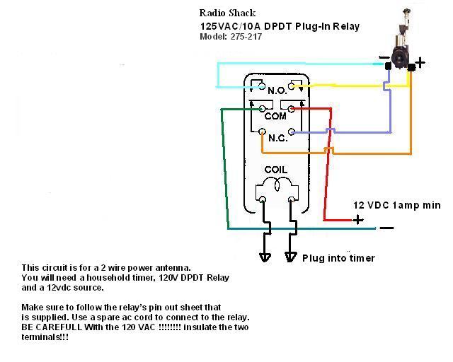
Thanks Rob!
Hope you are doing well..
I’m still waiting for my paycheck 🙂
I made one of these , but used a Intermatic timer model ST01C. Cut off or fold back the red and the green wire they are not used. The black wire is the load , the blue wire goes to the trigger switch, you have to reverse the timer in programing or the timer will trigger the door to open at nite and close in the morning, Intermatic has a telephone support that will walk you thru that . The timer is powered by a lithium 3 volt camera battery that they say will last 3 years or more . If you do have to change the battery, they said the programing remains, you may have to set the time of day as in current time back up. I also used a 12 volt deep cyle battery to power the antenna . I use a solar charger on it to keep the battery charged . Timer cost 30$
antenna cost 5$ , tracks for door 10$ , cutting board for door ( harbor frieght) , there was 2 in the pack the thicker one actually fits the tracks very well.
assorted other stuff 20$ ( screws , nuts, PC-11 epoxy )
Hey Chris,
That’s a great simple idea! I looked up the timer and I see that it does not need 120VAC, just the 3 volt battery to operate like you said. So any voltage can be switched. That is way better then an appliance timer circuit because you would need a relay and two seperate power sources.
I hope others read this post. It sure is a big help for those that do not want to mess with the photocell circuit. BUT remember everyone, you need to use a power antenna that has THREE wires (a trigger wire).
BTW Chris, did you get the antenna idea from here, or did you find it elsewhere first?
Thanks,
Bob
I got that from here, and looked at it and thought,…, hmm must be a simpler way.the only concern I have is, the chance of a bird getting caught in the door…the antenna i got you can not stop , it would most certainly kill a bird, the red wire from what I can tell could be used to trigger voltage to a relay? perhaps a relay that went to a small sensor so if something was in the door it would stop it? just a idea…I also liked the cutting board door better, it slides very easy, and the alum channel that is found in most hardware stores in that standard selection of channel, angles and flats that is a display, set in most hardware stores, that channel fits the board perfectly, and because it is like a skid , it will never stick.
The only caution was the temp range of the switch at about 20 deg it could start sticking they said. So an area that was well above that would be best to mount the switch in. Also they said to keep a eye open for a CT-1000, they are bringing them back into production again..
Oh the coolest feature of this timer was the astro feature, it ajusted automatically to the difference in the daylight hours during the seasons so it will allways close at a hour after dark , regardless of the time of year 9or what ever time you set it to after dark,) same for the other end , changes the open time as well…
Wow, that is really cool!
Seeing that it replaces a wall lamp switch, I would have never thought that it would have a “daylight difference” sensor. That’s one reason why I wanted to stay away from a regular house timer. Allways touching up the time to day light length. The other reason is because of a 120V power failure. Looks like this thing covers these two concerns.
I know the antenna can be quite powerfull, but I think they move slow enough that it would give the bird enough time to get out of the way. Unless they sleep under it. Opening would never be a problem. And if it closes when it’s just at full dark, all the birds would be in.
Thanks Chris for sharing,
Bob
Bob
Looks like the relay works, but there seems to be one small problem, I followed the diagram as it indicated, the door will open and close like it should at the desinated times but for some reason the motor stays running until you disconnet the power, then you can reconnect the power and when the door works again the motor once again keeps running when the door stops.
I thought that the relay would switch off the power, but looks as if it is not doing that.
Any sujestions?
Regards,
Rodney
Hey Rodney,
I’m happy you got the relay circiut built! It sounds like you built the circuit correct. The relay cannot shut down the voltage that it is sending. It does not know how long to send voltage. It is only a relay. As you see, it can only send + – or – +. It sounds like your antenna does not have a “duration shut off” like most power anntenas.
I can’t believe that someone designed a power antenna without a duration circuit built inside. I know you said it came with an on/off switch. It looks like they want the user to sit there and watch the antenna come out and turn it off manually. I do not know anyone that moves their antenna in their car up or down with a seperate switch in their car. With the antenna that you have, you would need to design sensing circuits at the door that would tell other circuits to stop the movement.
You see, that is the whole reason why I chose a STANDARD power antenna that is controlled by the radio being on or off. Because at it’s end point (in or out), it runs for a second then knows that it should stop moving until the voltage changes again. It’s built in the antenna.
Rodney, I’m sorry but I can’t help you continue. You would need more sensors and circuitry to get that type of antenna to work. You would be WAY better off bitting the bullet and find one with a trigger wire (3 wires total) You can find them on the internet between $15.00 to $35.00. Depending how much you search to find a deal.
Don’t give up! It’s well worth having this system.
Bob
Chris,
Do you have a picture of your setup?
I will get some pics together in a few days, it was really quite simple to build , perhaps i will find a host pic site and link them , or i will figure out how to host them off my site.
I had originally planned on building the drapery motor door, but now I like Chris’ setup better. So I’ve bought the Intermatic ST01C like Chris’ and now I’m off to the junk yard to search for an antenna. Are there a few car models that you would advise to get an antenna from? Also, I’d like to run the antenna in Chris’ setup from the coop power outlet since I don’t want to mess with batteries and charging. How would that be done?
Thanks.
Bob hope it is ok for me to answer this ………
Vadgo..
You could get a inverter that powers 12 volt, be aware, the antenna’s draw about 4 to 5 amps , also you need a 3 wire antenna , you can sourse a antenna that is 3 wire form Ebay for about 35$ or less . what you have in the wiring of that antenna is a red wire (+) or hot a black wire (-) or ground, and a trigger wire blue that triggers the antenna to go up or down accordingly, also, the intermatic timer is preset for the factory normally to be in the right configuration for the off on with the relay set up, mine was the exception. The color codes could be different in a different model antenna of the wiring , but they process the current in the same manner, or would have the same schematics . ( Hopefully I will be able to get the pics of the project uploaded today).
This is the only 3 wire antenna I could find on ebay. this is a Ebay Store as well,
so, I would assume that this link would be good for a while ,
If not here is a direct store link for future.
I have no affiliation with this seller what so ever…….Just trying to help those that may not be familiar with the ebay stores search option..
Greeting from Stevens Point, WI. Right in the middle.
I am looking for the companion invention…The machine that automatically empties my trap of live and very angry coons! My children think they are cute until they get close. I am up to about a dozen. My neighbor got 25, but he is an exterminator.
Of course now that the coons are under controll the hawks have moved in…At least the bald eagle has yet to swoop down to ground level. And the fox still patrolls at will. Seems free range means free lunch for our wildlife!
Thanks for all the ideas.
http://yfrog.com/05dsc04119qjx
Here is the link to the pics, and several notes,
the tracks are attached with sheet metal screws that have tapered heads I used a large drill bit to counter sink the hole so the heads set flush in the track, be carefull you do not over do it in the depth or size of the counter sinking,
The switch I mounted Outside the building,
(Caution this switch is said to have issues at temps lower than 20deg , you may want to mount it inside the coop)
so as to enable me to open or close it without entering to coop. it is in a weather proof box as pictured. The antenna was mounted with stud bolts to the wood frame ,
I would suggest you bring your antenna with you to size them correctly at the hardware store.
also, I cut off the antenna drain hole pipe as it was in the way and would not let the antenna sit flush in the mount board.
I did PC11 the outside of the top and bottom of the rails to the wood frame for stability.
also to attach the antenna to the cutting board door , I got 2 very small eye loop screws I used a pair of locking pliers to lock to the antenna knob top and another to the shaft of the antenna next to the top knob, I then unscrewed the top knob, removed it drilled two small holes into the cutting board about 1 in apart and screwed in the eye loop screws threaded the antenna thru the eyes of the screws , then, I screwed back on the top of the antenna, made sure the antenna knob was snug against the eyes and PC11 the end of the antenna to the eyes loops and the cutting board door and made sure that none of the screws , antenna knob, were left uncovered so it was totally encased in PC 11 epoxy . see the photos .
(Side note ) …to keep the antenna extended during the removal of the top knob, you will have to have it powered, and power to the sensor wire also, or you will have to extend it then remove the ground wire , and then the other red and sensor wire, then it will stay extended.).
You do not have to worry about the antenna not retracting all the way in like it did before you mounted it to the board, because it will retract as far as it can, and it has a time out feature , that simply stops it after so many sec of trying to keep retracting, the same with the extending, it will time out.
When you go to set up the door and door tracks , extend the antenna all the way and set everything up from that point.that way you will have a full retract, and a full extend. I prefur the battery method to a converter 110 to 12 volt, I want my door to be able to be opened if there is a power falure with the local power company.
I hope that helps, I will check back to see if there are any questions.
Very nice job Chris!
That shows that you can use ways to get the job done without being a machinist or an electronics engineer.
If I may make a comment; I would try to build the project so that the stroke of the antenna is as close to being full length as possible. In my opinion, it would put less stress on the motor and the plastic/nylon gear chain so that it is not forced to stop.
Speaking about stress;
I was thinking about the longevity of the power antenna. Maybe a little pre-planning will make our antennas last a bit longer? So far I have only witnessed one antenna quit on a car. The motor was fine, but the plastic/nylon gear chain had finally worn out. I think it would be an advantage to “counter balance†the weight of the door. Even a light weight plastic board or aluminum sheet is work for the antenna.
I mounted a pulley above the door and connected a string and a weight (that weighed the same as the door) to the door. The antenna actually sounded and seemed to move more freely. It was on my old coop. I no longer have it connected on my new coop. But I think it would be a good thing to connect it back.
Just gotta get out there and do it ïŠ
Thanks,
Bob
Oh,
Chris wrote “Bob hope it is ok for me to answer this ”
Guys, this is not my web site. Rob is the moderator and owner. I am just sharing my project and he has created this site so that we all can share and brain storm together.
about the stroke of the antenna,…
I did build this with it fully extended, what I was trying to say, but did not make it clear, was the antenna by being attached to the board does not retract back to its factory full retract position, the two after market antenna units I have seen so far, have a type of clutch system, so if it pulls back , and does not retract all the way ( that extra 1 to 2 inches taken up by the attachment of it) that is ok, the antenna runs for 5 sec or so like it does when it fully retracts, and then times out.
The same is true for the downward stroke when it fully extends , and reaches the end , it runs for about 4 to 5 secs , like it did before it was mounted, and then times out, that is part of the design of the antenna.
I liked this design better than some factory models , because if they did not extend fully they would then retract, the same was true for the retract, if they did not retract fully , the unit would then send the antenna back to the fully open position. That could be a problem after mounting the door to the antenna, because the antenna then could not retract back to what the antenna would sense as fully retracted, and send the door shut again.
I like the counter balance idea I will have to try that .
I got ya Chris. Good points. There may be no difference on stress no matter where the antenna gets stopped. That would give people more flexibility to have a shorter stroke if they were limited on construction / coop size. This is yet another reason to only use these types of 3 wire antennas.
Thanks,
Bob
Great discussion everybody! Lots of fantastic information here and I know there are a LOT of people are reading this article and these comments for ideas.
Keep up the good work!
I got my car antenna and hooked it up to a battery to test it out. The motor wants to keep running until the power is disconnected. I’m assuming it came out of a car that had a manual switch for up and down. Will this antenna work for this design or should I “punt” and get a new antenna?
is it 2 wire or 3 ? if it is three after 5 to 15 secs it should time out and stop … If it is 2 wire, I would punt and get the antenna shown on ebay in the link above in one of my previous posts. But thats just me, you could build the timer unit also shown in the above posts…Good Luck
It’s a 3 wire. I’ll try and run it a little longer and see if it stops. Thanks.
Yup,
If a 3 wire antenna does not eventually stop running, I would think that it’s “auto stop circuit” is defective.
Chris,
I just got a call from the salvage yard that they have an auto antenna, but it’s only 2 wire. Can I use that?
Thanks
Chris,
So the 12V converter, does it need to be 12VDC 4A rated? All of the ones I’ve seen are mA rated. Thanks.
I’ve been looking online trying to find the cheapest possible antenna, but it is hard to tell from the pictures if they have 3-wire or not. I found a Pyle PLNT90 and legacy LN46 and LN48. Would anyone know if any of these have 3 wire?
Thanks.
Vadgo,
As stated in the previous, the 2 wire antennas will not work with our designs without adding relays and more circuitry.
Vadgo,
You need at least a 1.5 Amp (1500 ma) converter. The more the better. I checked my current pull and read 1.5 Amps on my meter. What do you think Chris?
The antennas that you mention say that they are fully automatic. Even though I can’t see the wires either, I would bet that they are 3 wires. I think the key word is “fully automatic”.
Right now one ebay for “buy it now” $22.00 is
http://cgi.ebay.com/UNIVERSAL-AUTOMATIC-POWER-AM-FM-ANTENNA-HEAVY-DUTY-EA48_W0QQitemZ120477819846QQcmdZViewItemQQptZLH_DefaultDomain_0?hash=item1c0d09a3c6
My tests of the antenna for average draw indicated that when the antenna was timing out it would draw up to 2.5 amps. I imagine that would depend on the maker of the particular antenna you have.It is my understanding that all 3 wire antennas have the time-out/clutch system in them. I will be checking this late tonight for further questions.
I just tested another antenna and it has the exact same draw as Bob stated 1.5 amps , so who knows…? Maybe to be safe, just get a 2,000ma converter , or If you can not find one, use a 1.5.. it may work just fine for the brief 25 secs it takes to close the door.
Okay. I had the drapery motor set up for one week until the counterweight got caught on something and burned out the motor. This would be a better system but I’m not at all familiar with wiring but am a fast learner. SO, if I want a setup with the antenna hooked to a timer and an extension cord could someone help me out? And do I understand that I wouldn’t need the full extension/retraction of the antenna? I don’t have that much space for that. Thank you for a great exchange of ideas from such clever people!
Hi Mary,
We can help you. Chris has a nice system with a store bought day light sensing unit. You can go that route or with a couple of appliance timers which would be more “plug and play”. Either way you will need the 3 wire antenna. I’m sure you read all of the previous posts.
Bob
Thank you, Bob. First step is getting my hands on the antenna, then I’ll start asking more specific questions. I’ve read all the posts, but being a girl I don’t deal well with abstracts. I need to actually SEE it.
Just out of curiosity. Why doesn’t the system work when just the photocell is connected between the third wire from the antenna and the battery?
Hi Mike,
Great question!
You had me thinking for a moment because the antenna’s trigger sensor pulls so little current. Therefore it would not destroy the photocell if it were in series with it.
The theory may work but here is why I did not choose that method;
A photocell alone will not create a complete “on and off†connection. It slowly changes resistance from low to high. Now, that still may work. At some point it may stop the current from flowing to the trigger circuit. I guess you really don’t have much control over it.
BUT here is the main problem; the antenna needs to be extracted for the coops door to close. That means at night, the antenna’s trigger needs voltage in the dark. In the dark, a photocell’s resistance is high and would not let the voltage through (if it worked by itself). We need a circuit that creates the opposite switching. That is also why there is a relay in the complete photocell circuit.
Thanks for stimulating my mind!
Bob
My new antenna is on it’s way! I haven’t been able to find a 12V 5A power supply to fit my budget. But I did find a 12V 2.5A one for $5 bucks, so I’m going to try that one. I can’t wait for that antenna to get here so I can get started. And I’ll come back for help as to how to hook it all up.
I have my antenna finally! It has a red wire, a green wire, and black wire with a little thingy that looks like a circle (screw onto something?). How do I go about connecting the wires to the intermatic timer and the power supply that I have? Please know I really know nothing about electrical, and I probably need step by step instructions. Do I need to test the antenna first somehow?
Thanks.
the black wire with the circle is ground that goes to the Neg – side of the battery / 12 volt connection , Guessing the red wire is the hot or + that goes to the hot or + side of the battery or 12 volt connection.
the green wire should be the sensor wire, look at the instructions that came with the unit to determine what wire is the sensor wire. If you hook up the black to ground and the red wire to the hot or plus side it should do nothing, but when you then connect the sensor wire to the hot or plus side of the power source the antenna will open… as soon as the senor wire is removed from the current , it then retracts the antenna.
test this to make sure it works in that manner. If you scroll up into the past instructions , you will see there are photos and instructions on the timer already posted. as well as , photos of the door and how it is constructed.
Hope that helps
Ok, so these are probably stupid questions. I’m using a 12V converter, so how do I tell which wire is the – side of the converter? The antenna instructions are so bad (they are a black and white photocopy) I can’t really read them or the diagrams. So can’t tell what wire is supposed to be what. If the red/black wires aren’t the -/+ ones, that wouldn’t ruin the antenna if I hook them up backwars, would it? Don’t want to fry the thing messing with it.
So you’re saying test the antenna first before I mess with adding the timer?
I can never get your pictures of the door to open. The browser always times out, so I haven’t looked at how you built it. I’ll give it a shot tonight and hope I don’t electrocute myself in the process.
Hi Vadgo,
The green wire is the sensor.
I’m actually not sure if you will damage anything if you have your polarity reversed. It obviously wont work that way until you would correct it. I would feel more comfortable if you find out which wires on the converter are positive and negative. I’m trying to figure out a way for you to find this without a voltmeter. Do you have anything laying around that takes 12V ? (except light bulbs).
Any ideas Chris?