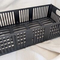
One of the common discussions on our printer forum is in regard to the “waste tank” that lies within many inkjet printers.  These “tanks” are actually just ink pads that absorb and then become saturated with ink.   There are a few ways ink becomes deposited on these pads including overspray during borderless printing, printing when paper jams, etc.  Usually the vast majority of ink is from the cleaning cycles when the printer literally sucks ink from the nozzles of the printhead.  You can imagine that after lots of print cycles quite a bit of ink is left inside the printer.   One of two things ends up happening:

  1. Your printer throws an error telling you your waste tank is full
  2. You end up with a black gooey mess leaking from beneath your printer

A wonderful member of our community, ghwellsjr, shared his experience in dealing with this problem.   I was so impressed with the detail of the images and information that I asked if I could share it on the site and he acquiesced.  :) Read more

canon-i960-printer

A few weeks ago I received the following email:

“I’ve written a procedure explaining how to remove a Canon i960 printer from its cover and base and how to prepare it to be operational while out of its case. It’s a 4 page PDF – 1 graphic, 3000 words, 36 paragraphs. Too big for a comment. If interested I’ll email it to you as an attachment.”

Well, I gladly replied that I’d love to see it. Below is the contents of the PDF and hope many find it useful. Thanks David for all your work putting this together!

“I find the Canon i960 printer manual lacking in practical information about inspections, tests and cleaning. This procedure explains how to remove the top cover and base and how to prepare the printer to be operational while out of its case.

Basic tools for this job are a medium size phillips type screwdriver with a 5-6 inch magnetized blade. Most hardware stores sell a simple magnetizing device for this purpose. Two straight blade screwdrivers – medium and small. A regular screwdriver with a sharp tip to pry apart connectors. Letter opener. Flash light. Container for small screws. Newspapers. Paper towels.

To remove the top cover: Turn the printer power on. Let it stabilize. Open the lid. The print head will move to the center. Pull the AC plug AT THE PRINTER. Pull out the USB cable. Remove any paper.

Remove the panel that holds the power/resume buttons – 2 screws. Unplug the cable from the button panel. Pry the connection partially apart, then grasp the conductors and pull with a rocking motion. Set the button panel aside. At the rear of the printer remove the inspection plate. Set it aside.

Look for 5 horizontal slots midway around the perimeter of the case. Use a flat blade like a letter opener to depress the internal plastic release tabs while pulling up on the open top cover. After the top cover is snapped loose, close the lid and rear paper rest. Grasp the top cover by each side and lift it from the base in a rocking motion. Set it aside. A cover over the USB connectors lifts out after removing the top cover. Set it aside.

A push-button switch at the top-center of the logic board senses the top cover lid opened or closed. Its normal state (closed lid) is NOT depressed.

If removal of the printer frame from the base is NOT required, reconnect the button panel and cable connection and temporarily install the panel on the base using the bottom screw. With the cover removed paper is not supported. Make a paper support. Cut a 7×9 inch panel from a corrugated cardboard box and insert it about an inch into the gap behind the rear paper guide. Now normal operations are possible as though the cover was in place.

Before removing the printer frame from the base, preliminary measures should be taken: Arrange a work station

-garage bench, utility table, kitchen table – preferably well lit and at a comfortable height. Prepare two wooden blocks to elevate the printer above the work surface. Lego blocks might work. Have newspapers and paper towels on hand.

For a test lash-up, cables from the power supply module, the button panel and a base test plug must be re- configured. It’s not necessary to disconnect them from the logic board or disturb the wiring runs.

Remove the power supply module and the power cable from beneath the base: Turn the printer around so the rear of the printer overhangs the edge of the work bench 3 inches. The power supply module resides in a recess beneath the rear of the base. At the end of the module towards the AC connector is a 3/4 inch wide plastic tab. Pry it away from the end of the module while grasping it near the AC connector. The module will drop out. At the other end of the module is a 9 wire plug. Pry/pull it out. Set the power supply module aside. Pull the power cable and plug back up to the top side of the base.

A cable of 8 red wires terminates on an open plug at the right rear corner beneath the printer base. It serves no purpose for this operation but must be dealt with because it’s fastened to the base. From above bend some of the red wires facing the rear to mark that side. To disconnect it from the base compress the locking tabs of the plug from below the base and pull it out from above. I used a medium size regular screwdriver and pried against a tab from below on one side while pulling up at a slight angle on the wires. Then I moved the screwdriver to the other side and did the same thing. The plug came out easily despite the tight spot. Leave the plug dangling. Turn the printer around.

At the front of the printer above the paper discharge chute is a 12 inch plastic bar. Removing this bar allows more maneuvering room to install or remove the printer frame from the base, but it’s not necessary to remove it.

It’s held in place by vertical latch tabs at both ends. Grasp the left end of the bar and push firmly to the left and upwards. On the right side on the end near the black purge pump look for a 1/2″ tab that extends downward. The tab must be pried towards the purge pump while lifting upwards on the bar. Set it aside.

The printer frame is held to the base by 2 screws located in the rear and 2 tabs (not visible) in the front. On the right rear corner a screw is located directly downward in line with the slot used to depress an internal plastic tab. Look down over the edge of the base with a flash light and use a magnetized phillips screwdriver to remove the screw. On the left rear corner the screw is located in line with the white fiber gear. It’s visible and easy to remove. Ignore the other screw nearby.

If the button panel was temporarily installed earlier remove it now from the base and unplug the cable. Look for the U-shaped metal bracket at the right side near the purge pump motor. For future reference, make a mark on the vinyl covered button cable at the center of the purge pump motor. Remove the bracket – 2 screws. Arrange the button cable so that it is free from snagging when the print frame is lifted from the base.

Grasp the printer by the metal tabs on either side of the center frame and lift upwards favoring the left side. The front holding tabs are cleared by pushing the frame slightly backwards after the rear clears the base a fraction of an inch. Jiggling the printer frame may be necessary. Avoid handling the frame at any other points. It’s easy to damage fragile parts. Once clear of the front tabs the printer should lift free from the base but watch carefully for any overlooked connection or obstruction. Set it down.

On the printer base look for any foreign objects (screws, clips, springs etc.) and save them. Remove the white plastic bar with teeth from the printer base and set it aside. The printer base and waste ink pads will be cleaned later.

On the printer frame there may be dust/debris in areas that are now accessible. If you have access to compressed air, this is the time to blow it out. Leave the print head away from the purge area. Don’t blast ink from the purge area onto other parts.

Prepare the printer to operate outside of its cover and base: Put down newspapers. Elevate the printer base on blocks. Make sure a folded paper towel is below the black purge pump near the right front corner.

Plug the button cable into the button panel and place it in a convenient location. Plug the 9 wire power supply

cable into the loose power supply module. Plug in the USB cable from the computer. Insert the 7×9 cardboard panel into the gap behind the rear paper guide. Load some paper. Remove the ink cartridges and visually check for ink levels. Reinsert them and move the print head back and forth a few inches by hand. It should move smoothly. Confirm that the print head locking lever is down. Plug the AC cord into the loose power supply module.

Turn the power on. Look for the green light. There will probably be print head movement and purge activity. After the printer stabilizes, depress and hold the open lid button on top of the logic board. The print head should move to the center. Release the button. It should return to the parked position over the purge unit at the right side. There might be ink on the folded paper towel.

Turn the COMPUTER on. After boot-up go to Start/Settings/Printer. Right-click on the i960 printer icon. Go to Properties/Print Test Page. The printer should print the test page. Click on the Maintenance tab. Do a nozzle check.

At this juncture there are many things to check for, depending on conditions and symptoms. It’s beyond the scope of this procedure to list them but if cleaning, lubrication and repairs are to be made, this is the time. If any clips, screws, etc. were found in the bottom of the base, this is the opportunity to determine where they MIGHT belong.

Clean the waste ink pads: In the base are two pads on top of each other running 11 inches along the length of the base. Two small pads are on top of each other near the purge pump area. There’s also a pad at the far left of the base that’s probably not stained. Remove it too. Set it aside. The others are very messy. Take the base to a laundry type utility sink or a bath tub. Put on rubber gloves and remove the pads. Don’t do this on the driveway unless you can live with the stains.

Place them under a running faucet or direct a warm water stream from a hose to flush them out. Using your gloved hands, press the water out, flip them over and press the other side. Repeat this until the ink no longer blackens the water pressed from the pads. Be careful not to damage the small ears on the big pads. The stains can not be removed but the bulk of the ink will be flushed out. Leave them soaked with water so they dry out to maximum thickness. Place them on 4-6 layers of paper towels, preferably outside in the sun. Flip them and change the towels every few hours. It might take 2 days for them to dry.

Flush the base under a stream of warm water to remove the ink. Clean the printer top cover with soap and water. Use a spray bottle of bleach type cleaner to remove stains from the sink or tub.

To re-assemble the printer gather all the parts that were set aside in one location. Keeping an eye on them will guide you what to do next and in what order. Start with the base. After the waste ink pads are dry, install them. Start with the small ones. The bottom pad may be of different material than the top one. Install the single pad previously set aside. Install the big pads. There’s a slight difference between the bottom and top pads. Install the white plastic bar with teeth on the base. It fits only one way.

Disconnect the loose power supply module from the power supply cable and the AC cord. Disconnect the button panel from the button cable. Remove the paper and 7×9 cardboard panel from the rear paper guide.

With the base and printer prepared, lower the printer onto the base: First, position the button cable so that the reference mark is near the center of the purge pump motor. To hold it from flopping, place the button cable above the metal tab that anchors one side of the U-shaped bracket. Tape is optional. Grasp the printer frame by the tabs on either side of the center frame. The rear of the printer has to go slightly back beyond the screw holes so that the 2 front tabs are engaged when the printer is then brought forward. It might require some jiggling. You can tell if the printer frame is seated properly when you can see the rear holes firmly against the bottom case and are lined up. Confirm the button cable is in the slot at the bottom rear of the case. Attempt to lift up the front of the printer frame at both corners. It should be secure under the tabs.

Install the U-shaped metal bracket on the right side – 2 screws. It has a retainer tab for the button cable which should now be positioned correctly with the center of the purge pump motor in line with the mark made earlier. Use the magnetized phillips type screwdriver and install the 2 screws that secure the rear of the printer to the base.

If not already in place, install the 12 inch plastic bar across the front of the printer above the paper exit chute. The thick side is to the left and the 1/2 inch tabs point downward. Push the bar down from the top until it snaps into place.

Turn the printer so the rear of the printer overhangs the edge of the work bench 3 inches. Install the red wire cable plug into the square hole at the right rear corner of the printer base. The bent wires face to the rear. Push the plug down from the top side of the base into the hole until the plastic tabs snap into place.

Route the power supply cable and plug down through the opening in the right rear corner of the base. Plug it into the power supply module. Snap the power supply module into the recess beneath the bottom of the base. Set the USB cover plate in place. Turn the printer around.

Install the top cover loose. Route the button cable and plug up through the opening in front of the clear mist shield. Snap the cover down starting with the left side. Insert the button cable plug into the socket of the button panel. Open the lid. Fasten the button panel – 2 screws. Close the lid. Install the rear inspection plate.

Plug in the AC cord and the USB cable to the computer. Load with paper. Turn on the computer and printer. Wait for everything to stabilize. Open the printer lid. The print head should move to the center. Check the ink cartridges. Make sure they have ink and are seated properly. Confirm that the print head locking bar is down. Close the lid. At the computer, navigate to the printer icon and print a test page. Click the maintenance tab and do a nozzle check. Print a test color bar or photo.”

A HUGE thanks to David for sending this great writeup over!

NOTE: If any visitors give this a go please post your thoughts below and take lots of pics during the process so we can add them!

Refill BCI-3/6/CLI-8 PGI-5Bk cartridges using the “German Durchstich” method

This is a refill method suggested by our forum member pharmacist.  I haven’t had a chance to test this method yet, but it does look interesting!   NOTE: This has only been tested with refilling Canon OEM Canon cartridges.  I’m of course concerned about ink leaking out and/or air leaking in.   I’m also wondering if this only works with carts that have a specific design and/or specific type of lower sponge.  Canon carts have a tight sponge where some of the non OEM carts have a very loose / porous sponge.

Below are pharmacist’s comments and images regarding this method:

“It really works great and I already refilled my PM cartridge for the 6th time now (the cartridge you are seeing on the pictures I made). So far: not a single drop of ink is coming out of the refill hole (maybe some staining on the plastic back of the printhead, but this is negligible). I have to say: this method is only thoroughly tested on original Canon carts (BCI-6/CLI-8).

The first time I did this I was amazed that not a single ink is coming out (I was afraid too like you !) of the refill ink: but I was concluding if ink would come out of this hole then it would be also from the ink outlet beneath it, and we all know -with sealed carts- it won’t. But I cannot guarantee it will work with aftermarket carts. I do not experience with air leaking at all when printing sudden large area’s with the same colour whatsoever. It works great with original Canon carts.”

http://www.nifty-stuff.com/forum/uploads/2251__mg_0105.jpg

http://www.nifty-stuff.com/forum/uploads/2251__mg_0106.jpg

http://www.nifty-stuff.com/forum/uploads/2251__mg_0107.jpg

http://www.nifty-stuff.com/forum/uploads/2251__mg_0108.jpg

http://www.nifty-stuff.com/forum/uploads/2251__mg_0109.jpg

http://www.nifty-stuff.com/forum/uploads/2251__mg_0110.jpg

http://www.nifty-stuff.com/forum/uploads/2251__mg_0111.jpg

http://www.nifty-stuff.com/forum/uploads/2251__mg_0112.jpg

http://www.nifty-stuff.com/forum/uploads/2251__mg_0113.jpg

View larger versions of the images and discuss this method on our forum here.

laser-toner-refill

My Experiences With Laser Toner Cartridges (Refilling and Remanufactured)

I’ve decided to chronicle my experiences with laser toner cartridges over the past few years. I’ve had a hand at refilling toner cartridges and have also used remanufactured (refurbished) cartridges.

My first experience was refilling an HP toner cartridge at one of my past employer’s. The company was on a shoestring budget and I felt like this could be a good way to save us some money.  I purchased a refill kit online that contained instructions, toner, a tool to burn a hole into the cartridge (simply a soldering iron with a copper tubing end cap) some aluminum tape to cover the hole, and a special toner cleaning cloth.  It was a pretty easy process but potentially pretty messy… if you’re a first timer be sure to do it outside.  I was able to get at least 3 good refills with this kit for the HP toner cartridge I was refilling.

In August of 2005 I noticed my cartridges for my personal printers were having problems so I purchased remanufactured cartridges for my Laserjet 4 and 6P  on eBay.  The prices were amazing, almost the lowest I could find anywhere.   You could also try toner refill here.

The 6P cartridge worked flawlessly, but I did have some issues with the other cartridge. The first LaserJet 4+ they shipped was either sent broken, or broken during shipment and the mylar / metallic bag the cartridge was shipped in was full of toner.  They promptly sent me a new cartridge at no cost.  This cartridge was in good shape, but the first prints had a bit of image ghosting.  I think it was because I had the intensity set too high on my printer.  After adjusting a few settings the ghosting went away.  I used this printer a lot and about 7 months later it started to say “toner low”. Around that time I also started to get a vertical line down the far side of each page printed.  I believe the wiper in the cartridge went bad.

Well, it was time for another cartridge.  I was in a hurry so I thought I’d give Cartridge World a try.  I’ve heard good things about CartridgeWorld and have spoken with the owner of a local franchise a few times.   I exchanged 5 of the HP LJ 4+ cartridges I had sitting around and he gave me a good deal on a new cartridge.  Even after the deal the price was still 50% higher than ebay cartridge, but I’m expecting the quality to be much higher.

When this cartridge dies I think I’ll give refilling a try.  There are two main reasons for this:
1) To save some money
2) To really test how well Cartridge World remanufactures their cartridges.

The only issues with refilling is first knowing if the toner is a quality product, and second I don’t think I’ll be able to exchange a toner cartridge with a hole melted into it.  :)

I’ll update this page as I continue experimenting.  Until then, you can read more about toner cartridges on my forum here: Printer Forum.

Update: 6/2/07:
I ended up printing 10,468 pages with my Cartridge World cartridge.  Toward the last 300 pages I started to get light prints and so I played the “shake the cartridge” game to the point where I knew it was time to refill.  I used some toner from, you won’t believe this, a few bottles of toner I had purchase back in 10/2004!  I was almost reluctant to use the toner since it was about 3 years old, but I had kept it in a dark moderate temp place so I thought I’d give it a try.  Well, I’ve printed 1,200 prints with it and so far so good!

I’m not sure if this is a testament to the quality of the Cartridge World remanufactured cartridge or the quality of the toner I used, but my guess is that it is a combination of both.  Once this cartridge gets to the point of death I’ll probably go back to Cartridge World for my next cartridge… do you think they’ll take my abused cartridge with a refill hole in the top? Probably not. ;)

Update: 4/08:
My HP Laserjet 4plus had been a wonderful workhorse, but it began to have feeder roller issues.  Instead of spending hundreds to fix an old printer I purchased a new Brother HL-2170W from Costco about 4 months ago.  The printer had given me the “toner low” message even though the prints were super sharp.   I don’t like it when a printer tells me it is time for a new toner cartridge, but I’ve read that these cartridges actually use toner as a lubricant so running them dry could break things.   Anywho… I purchased 2 bottles of toner on ebay for $16.   Instructions said to completely empty out any old toner before adding new toner.  What I like about the Brother toner cartridge is that it has a plug that I just pull out to access the tank… no plastic hole cutting / burning!   Well, I dumped out the toner… a LOT of toner and then refilled it with the stuff from ebay and replaced the plug.   So far I’ve printed at least a thousand pages and things look fantastic!

Update: 9/09:
As I mentioned in the printer forum my inkjet All-In-One died.   I decided to buy a laser multipurpose machine to replace it.  I opted for the Brother MFC-7440N which is network ready… which also makes my wife happy because she can now print, copy, scan, fax without me having my computer on!   This machine takes the exact same laser toner cartridges as the Brother HL-2170W printer: TN330 or “high capacity” TN360 .

This article describes a cheap and simple way to vacuum fill Canon BCI-6, and similar cartridges. The only cost besides ink is a vacuum chamber and a vacuum pump. If you’re lucky, you can get a loaner manual vacuum pump from an auto supply store for just a few bucks or even free. That is what I did to develop this article for a total cost of under $30. Or, if you prefer, you can buy your own manual vacuum pump for about $40 or an electric one for $130. The manual pumps are designed for bleeding brake lines and the electric ones are designed for purging air conditioning lines. I bought this unit http://www.atdtools.com/showitem.php?item_id=3409 from a local auto supply store. I don’t believe it is available on line.

The vacuum chamber is available from http://www.inkjetsaver.com/vacchamber.html for $24.95 plus $4.99 shipping. It is really designed for filling cartridges with multiple colors and comes with several ports and tubes for this purpose. I just yanked the tubes off from the inside of the lid and put plugs on them. I called inkjetsaver (CompuBiz Inkjet) and found that you can special order the vacuum chamber with only one port or you can special order four extra screw-on caps that go on the unused ports on the outside of the lid for $.15 each. Either way you go, you just need one port open to connect the tube that goes to the vacuum pump.

Fortunately, the tube that comes with the manual vacuum pump has an inside diameter of 1/4″ which is the perfect size to fit snuggly on one of the ports on the top of the lid.

To get started, you need to put the original clips that came with your ink tanks (all of one color, of course) back on them. If you don’t have them, use electrical tape to cover the outlet ports. If you are filling Canon ink tanks, you can use rubber bands, like I did, to hold their clips in place.

Place the ink tanks in the bottom of the vacuum chamber upside down, that is, with the clips on top. Depending on the size of the clips, you can get ten or twelve cartridges in the vacuum chamber. If you don’t have enough tanks to completely fill the bottom of the chamber, use some kind of container filled with water to keep the tanks from falling over. Pill bottles work well for this purpose.

Next you want to add about an inch of ink to the chamber.

Put the lid on the chamber and connect the pump.

Here’s what it all looks like so far:

Pump until you reach at least 25 inches of vacuum on the gauge. It will take about three minutes. You will get a good work out.

Initial Pump Down Video

Slowly release the vacuum and watch the ink flow into the tanks.

Initial Fill Video

Chances are the tanks will reach about 80% full. As long as there is enough ink left in the chamber, you can repeat the process and attain almost 100% full, otherwise add more ink before repeating. Again, it’s time to take another three minutes of exercise. If you have an electric vacuum pump, you will be able to get almost 100% full with just one application.

Final Pump Down Video

Releasing the vacuum the second time looks like this:

Final Fill Video

It’s hard to see but the small space between the top of the sponge and the top of the cartridge gets full of ink by this process. When you remove the cartridges from the vacuum chamber, you should remove the clips from the outlet ports and set them in a location where you can afford to have the ink drain out and it will, as shown in this video:

Top Drain Video

The next step is to wash the cartridge by running water over it and then dry it with a towel. Then, blow a little air into the air vent to force some ink out of the outlet port and assure that the top of the sponge is not saturated with ink.

At this point, I stretch a piece of vinyl electrical tape across the outlet port and place the cartridge up-side-down on a counter top while squeezing the sides where the sponges are. The purpose of this is to drain the two wells that are in the serpentine path for the air vent. Continue squeezing until you no longer hear a gurgling sound and no more ink comes out of the air vent.

Whether you leave your cartridges with their original clips on or use tape, you should make sure that the outlet port is sealed until it’s time to install them in a printer. You should not seal the air vent because you want the cartridge to be able to “breathe” through its normal air vent as atmospheric pressure changes cause air to move in and out of the cartridge.

Here is a photo of the final filled cartridge:

Make sure you clean the vacuum chamber and lid after use.

Summary of findings on refilling Canon BCI-6 cartridges.

 Misc information

  • Some people say that with the availability of low cost non-OEM carts that there is no longer any reason to refill Canon inkjet carts.  There is some validity to this argument, depending on the value that you place on your time and your willingness to tolerate the extra effort required to refill carts.  It is not the purpose of this discussion to debate the merits of this argument.  It IS the purpose of this discussion to discuss alternate refilling methods that may function better than existing techniques for those who are inclined to refill their own carts.
  • Based on measurements of the inside dimensions of a dissected non-OEM cart, the “Ink Chamber” has a capacity of 6.4 CCs.  The “Sponge Chamber” has a capacity of 9.6 CCs up to the top of the upper sponge, without accounting for the loss of capacity due to the sponge and filter.  This gives a maximum total capacity of 16 CCs.  One non-OEM box claims 15 CCs, which is reasonable if they completely fill both chambers with ink, which many suppliers don’t.
  • The “bottom sponge” has a volume of 5 CCs, and this sponge is usually still almost full when the ink chamber empties.  Since Canon recommends replacing the cartridge at this point to keep from running out of ink (the printer keeps sending warnings), a completely filled cart will only give 10CCs of usable ink.  Most of the new carts that I have seen will only give about 7-8CCs, judging from how much of the upper sponge is empty when they are new.
  • It is today’s prevailing wisdom that these carts can only be refilled a limited number of times before something happens to the sponge (it dries out?) that prevents the cartridge from operating properly.  I have listed some other possibilities that could also cause this problem:
    • The “filter” may not always drop back down to its proper position when the cart is removed and may not make good contact with the ink pickup on the print head when the cart is reinserted.  This can be fixed with a few sharp taps of the cartridge onto a hard surface.
    • The “fluid link” between the filter and the bottom sponge is lost.  It is not guaranteed that ink will flow through this interface unless the interface between the two parts is kept filled with ink.  If this interface “dries out” for some reason, the cartridge can be full of ink and still not deliver any ink to the filter.  To check this, blow into the vent opening on the top of the cart with the exit hole uncovered (after making sure that there is no sign of any ink on the vent opening) – use about ¼-½ of the pressure used to blow up a balloon.  Ink should drip out of the exit – at least 1 drop/second.  If ink doesn’t start to flow almost immediately, the filter is being starved for ink and may not be delivering enough ink to the print head.  Blow into the vent with about ½ of the pressure used to blow up a balloon until the ink starts to flow.  Note that the sponges and filter can develop quite a resistance to the ink flow and they will often “push back” some air when you stop blowing into the hole.  This can cause “blow back” you will sometimes see ink pushed back out of the vent when you stop blowing – be careful not to get any of this ink on you.  After using this procedure, let the cart drip for a few minutes, then dab away any excess ink at the exit and vent before putting the cart into the printer.  It is best to wait 20 minutes or more to let the pressures fully equilibrate before using a refilled cart.
    • Air is getting into the bottom sponge – some air naturally enters the sponge each time a cart empties, and it is not removed during a conventional refill procedure.  This can be seen by simply comparing a new cart to one that has been refilled several times.  As more and more cells fill with air, the internal surface tension link between adjacent cells of the sponge can be broken, causing the ink supply to first decrease than eventually stop completely.
    • Most people throw the cart away when it exhibits any of these symptoms and replace it with a new factory filled cart.  This isn’t too much trouble if the factory filled cart uses the same ink formulation as your bulk refill ink.  If the inks are different and you are concerned about the quality of your colors, however, you really need to switch back to factory filled carts in all locations until you get enough empty carts to refill, then you can switch to refilled carts until you run out of empties again, then….. To minimize the number of times that you must make this switch, there are a few techniques that can be used to extend the useful life of your refilled carts.  A few of these procedures are discussed below.
  • It has been stated that if the viscosity of an ink is too high that this will cause an ink supply problem, and that the problem ink can be diluted with distilled water as a remedy.  This may fix a flow problem, but it will probably also noticeably change the colors that are printed.  See (“http://www.nifty-stuff.com/forum/viewtopic.php?id=65&p=4”) for a discussion and demonstration of the potential color problems that this can cause.
  • There are a number of other strange problems that can occur when the print head is starved for even a single color (“http://www.nifty-stuff.com/forum/viewtopic.php?id=103”).  There are various theories why this happens, but they remain to be proved or disproved.  In any case, the best solution is to never run out of ink!  The main concern about running out of ink is usually said to be that you can permanently damage the print head.  There are examples where this has happened, but it doesn’t seem to be a common occurrence.  The most common problem that I have seen or heard about is that it can take 5 or more “cleaning cycles” to get the ink flowing again, and you can easily lose ¼ of the ink in each cart each time that this happens ($24 of ink with Canon carts – ouch!).   I once inadvertently forgot to fully latch the Green cart into the print head, and it took 5 regular cleanings and a deep cleaning to get the ink flowing properly again, in addition to the 5 cleaning cycles that I ran before discovering the unlatched cart.  Thank goodness these were refilled carts, as I lost almost ½ of the ink in the carts because of a single careless mistake.
  • Some people recommend refilling a cart when it still has 6 mm of ink left in the ink chamber.  This means that they have to periodically pull each cart to see the ink level, since the printer’s “out-of-ink” sensor only senses when the ink chamber is empty.  In these cases, the cart should be quickly put back into the print head if it doesn’t need to be refilled.  If the cart needs to be refilled, it should be replaced with a cart containing the same ink and with sufficient ink for at least one cleaning cycle.  This will prevent the ink pickup on the print head from drying out or pulling in air.  The printer sometimes senses or otherwise decides that a cart has been changed and runs an automatic cleaning cycle to pull the new ink into the print head, so every cart that is put into the printer needs to have enough ink to prevent air from being pulled into the print head by a cleaning cycle.  The ideal solution is to have at least 2 carts of each color on hand at all times so that a full cart with the same bulk ink is always ready and can be used to immediately replace the empty cart.
  • If you are concerned about the color of your prints, always use a complete set of carts from the same supplier, or use refilled carts with bulk ink from the same supplier.  Inks are formulated to work together and mixing inks from various sources can easily upset the color balance of your prints.

 Alternative filling techniques to help to remove air from the sponge 

  • Several alternative refill techniques have already been posted at (“http://www.nifty-stuff.com/forum/viewtopic.php?id=28&p=6”).
  • The photo below shows how the needle can be sealed to the refill hole using some “tacky putty” that is available at hobby stores.  By SLOWLY pushing ink into the cart with the injection hole sealed, additional ink can be pushed into the sponge chamber (and hopefully into the sponge).  Make sure that the needle doesn’t touch bottom of the ink chamber so that the large part of the needle is tight against the cart to prevent the putty from being forced down into the fill hole.  The vent hole must be open and the exit hole sealed during this procedure to prevent ink leakage.  Hold the cap on the exit tightly in place by hand or with a strong rubber band.  Lift the needle slightly to break the seal and fill the rest of ink chamber when you are done pushing extra ink into the ink chamber.
  • The next two techniques use vacuum to remove most of the air from the cart and then let the vacuum pull ink into the evacuated cells in the sponge.  This may be the way that new carts are filled, judging by the ink patterns on the top sponge.  It is very possible that one of these (more complicated) techniques will only be necessary every 3rd or 4th refill to get the air out of the sponge, and that conventional techniques will suffice for the other refills.  Note that only the two vacuum techniques that showed promise are shown – there were at least 50 other attempts that failed.  You are encouraged to experiment on your own to see if you can develop improvements.  Be forewarned that these techniques can be a little messy until you get the hang of them.
  • Both techniques need some extra equipment if you want to try them:
    • You will need a vacuum pump and a vacuum chamber.  A low cost vacuum pump can be made using your car’s engine and a short piece of vacuum hose.  Most gasoline engines will pull at least a 20” vacuum at idle (30” is a “perfect” vacuum).  The problem with using a car engine as your vacuum source is that it has such a high capacity that it pulls its full vacuum on a cart almost instantly, and the ink foams uncontrollably.  The air flow could be controlled with some needle valves and monitored by a vacuum gauge, but a better solution is a simple hand powered vacuum pump.  This type of pump is sold to bleed brakes and was purchased at Sears for $35.  It comes with a gauge, hoses and assorted attachments.  It is rated at up to a 25” vacuum, but it can actually develop slightly more if you pump long enough.  There are more rugged (professional grade, rebuildable) pumps available at auto parts stores for about $80 if you plan on using this pump a lot.                                                                      
    • The previous photo also shows the top of a simple “vacuum chamber” – an empty pickle jar.  You want a wide mouth jar with thick glass and a metal lid capable of withstanding the pressures involved.  Punch a hole in the lid and enlarge it so that a fitting can be roughly screwed in (in this case, a ¼” pipe x ¼” barbed hose fitting).  Seal the fitting (both inside and outside of the lid) with silicone sealant and let it cure for 24 hours.                                             
    • If you come up with a better solution for a simple vacuum chamber, pass it on (a pressure cooker won’t seal against a vacuum).  Just remember that a large volume takes longer and is more work to pump down.  On the other hand, a larger chamber would allow multiple carts to be refilled simultaneously.  Note that the seal material on the pickle jar lid was designed for a one-time use, and that it will eventually compress with repeated use, so you may have to tighten the lid progressively harder to get it to seal.  When this happens, apply the same silicone sealant used to seal the fitting in the lid as a thin, uniform coating on the seal surface (allowing 24 hours to harden before using).
  • Vacuum technique 1:
    • Fill the ink chamber of the cart about 3/4 full, leaving the ink chamber refill home open.
    • Place some duct tape over the vent opening over the sponge chamber to prevent air from being pulled directly into that chamber when the vacuum is released.  Duct tape has a much more aggressive adhesive than scotch tape, but the surface needs to be completely dry and you need to put a lot of pressure on the tape to get a good seal to the top of the cart.  If the vent leaks, the sponge may not fill properly.
    • Seal the exit hole (e.g. using the caps that come with a new cart, held on by a strong rubber band).  If you have some of the new InkGrabber cart holders that were shown in the forum, they appear to be ideal for this use.
    • Mount the cart in the vacuum chamber so that it is held in its normal vertical position – a piece of modeling clay works well for this.  It is also a good idea to put some clay under the jar so that it doesn’t roll around and tip the cart over.
    • With the cart generally level, slowly pull a vacuum on the jar.  This clip shows a (somewhat shaky) demonstration of this process where the vacuum was pulled fast to keep the clip short.  As the vacuum is pulled, the air in the sponge chamber bubbles up through the ink.  When the vacuum is pulled slowly, the walls of the ink bubbles have time to get thinner, more of the ink bubbles have time to break and there is less ink lost to the bubbles coming out of the open injection hole than if the vacuum is pulled quickly.  When a car engine was used to pull the vacuum, almost all of the ink bubbled out of the cart within a few seconds because the vacuum was pulled so quickly.  My guess is that about 2-3 CCs of ink are lost to the ink bubbles with the hand pump – too much if we can only add 4-5 CCs of new ink.  Note the color of the sponge as the vacuum is pulled – it turns white, indicating that most of the ink has been removed.  Toward the end of the clip, it appears that some ink is pooling in the bottom corner of the sponge.
    • The next step is to release the vacuum to pull the ink in the ink chamber into the sponge, shown in this clip.  Tip the jar so that the cart is angled by about 45 degrees so that all of the ink will easily feed into the sponge and then slowly release the vacuum with the trigger on the vacuum pump designed for that purpose.  As the clip shows, the ink is very quickly pulled into the sponge.  It also shows that there is not nearly enough ink in the ink chamber to fill the sponge.
    • The photo below shows the cart after the refill cycle.  It is obvious that all of the ink in the ink chamber was pulled into the sponge.  It is also obvious that most of the ink ended up at the far end of the cart, not at the bottom.  To be a workable solution, it needs an external ink reservoir to draw from so that the ink will completely fill the cart in a single step when the vacuum is released.  This will also require a larger vacuum chamber to accommodate the increased height of the external reservoir.  I did not pursue this solution any further in favor of the second vacuum technique.  It is left open if someone else wants to pursue it.                                                                  
  • Vacuum technique 2:
    • Use the same pump and jar as in Technique 1.
    • Keep the refill hole closed and sealed, and tape over the vent using duct tape as above – sealing the vent is very important to get a complete fill of the cart.  This technique works even without adding a refill hole on new carts.
    • Leave the exit hole completely open.
    • Put the cart in a shallow, narrow tray that is slightly longer than the cart – shown below.  In this case, the “tray” is a piece of clear plastic “blister pack” used to package 3 molly anchors (found at Target).  It’s not perfect, but it was the best that I could find on short notice.  If anyone finds a better product for this purpose, please post it.  This tray needs to:
      • Hold at least 20 CCs of ink after the cart is in the tray.
      • Fit in the vacuum chamber.
      • Support the cart in a vertical position (scotch tape worked OK for this tray).
      • Support the cart so that the exit touches the bottom of the tray to pick up as much ink as possible, but at a slight angle so that the exit isn’t sealed against the bottom of the tray.
      • Be stable so that it doesn’t tip over – some modeling clay worked well in this case also.                                                 
    • Fill the tray with enough ink to completely fill the cart (15 CCs minus your estimate of how much ink is already in the cart), plus a few extra CCs.  Almost of the ink that is in the cart will be pulled out when the vacuum is pulled, and will be sucked back into the cart when the vacuum is released, so this ink must be accounted for to prevent overflowing the tray.
    • Slide the tray and cart into the jar, with the tray being tipped slightly toward the cart’s exit so that the ink will run toward the exit as the cart fills.
    • Pull the vacuum.  The degree of bubbling/foaming of the ink will depend on the ink.  The black foamed very little, but the other inks foamed quite a bit.  The photo below was taken while filling a photo magenta cart, and it shows quite a bit of foaming (the poor focus is because the camera focused on the jar, not the cart).  One of the main benefits of this approach is that there is a lot of surface area available to allow the foam bubbles to collapse without overflowing the tray, allowing the vacuum to be pulled more quickly without any loss of ink.  If the foaming starts to get out of control, wait a few minutes for the foam to collapse, then continue.                                            
    • Once you are at full vacuum, let everything sit until bubbles stop coming out of the exit – it can take a while for the sponge to release all of its trapped air, and it is important to remove as much of this air as possible.
    • Slowly release the vacuum, as shown on this clip on a PM cart.  Note that the ink bubbles collapse first, then the cart fills with ink.  When finished, the sponge chamber should be full of ink, but the ink chamber may not be as full.  Most of the remaining air in the sponge chamber apparently gets pushed into the ink chamber, preventing it from filling completely.  This can be minimized by:
      • Pulling as high of a vacuum as possible before refilling.
      • Making sure that the vent hole is well sealed before starting.
    • The photo below shows the PM cart that was refilled in the video clip.  The sponge and even the space on top of the sponge are completely filled with ink (the ink above the sponge was eventually absorbed into the sponge).                
    • If this fills the sponge too far for your liking, it is easy to pull a lower vacuum on future carts, and this will pull less ink into the sponge chamber.
    • Unseal the vent, and clear the vent channels (low pressure compressed air is fine for this).  Some ink should drip from the exit when this is done.
    • If you want to “top off” the ink chamber:
      • Seal the exit hole.
      • Open the refill hole
      • Top off the ink chamber as usual and reseal.
      • Remove the exit seal and let the cart sit until it stops dripping.
    • You can save the left over ink in the tray if you wish, but with the cost of bulk ink being so low, even a 50% loss isn’t that bad if this technique reduces your ink feeding problems.  Because the ink is pulled into the cart through the discharge hole in this setup, it is important to keep the ink clean to prevent contaminants from getting to the print head pickup.
    • With a slight modification, this technique can be used to remove the ink that remains in carts if you are changing ink suppliers or if a cart is being refilled for the first time and a different ink was in the cart.  This clip shows 3 carts being emptied together, with a PC cart toward the camera:
      • The 3 carts were tied together with a rubber band and placed into the jar.
      • The exits were open and the vents were sealed.
      • The jar was tipped so that the exits were slightly lower than the rest of the cart.
      • A full vacuum was pulled, pulling the ink from all 3 carts at the same time.
      • It is very important to tip the jar up to a vertical position before releasing the vacuum to prevent the mixed inks from being sucked back into the carts.
      • This procedure will not completely remove all of the ink in a single step if there is a lot of ink left in a cart’s ink chamber, and the procedure may not need to be repeated once or twice in that case.
      • There was a lot of foaming of these 3 inks.

Summary

I have now refilled 6 carts using the second vacuum technique, and each of those carts has been “sucked empty” prior to refilling.  Normally, this would be the kiss of death, but each cart that was refilled in this way printed without problems.  It is still too soon to make any firm statements about the long term success of this technique.  Others are welcomed to give it a try and see what they find.  The best way to see if it works is to take a cart that you consider to be “dead” and refill it according to these instructions.

 Misc Notes 

  • After a plastic refill syringe is used a number of times, it can become stiff and hard to move, making it difficult to control the ink’s injection rate.  You could suck some oil into the syringe to lubricate the seal, but this would contaminate the ink on the first few refills.  A better solution is to lubricate the seal from the back side by inserting a Q-tip that has been dipped in vegetable oil into the open end of the barrel.  It will be necessary to slightly bend the Q-Tip so that the end contacts the inside of the barrel, then rotate the barrel so that it is coated on its full circumference.  Pull the plunger out to get oil onto the seal surfaces, and then work it in and out to coat the rest of the barrel.
  • Refilled carts slowly “dry-out” as some of the ink evaporates through the vent.  This is why new carts are packaged in a sealed bag with the vent sealed.  To minimize the evaporation loss from your spare carts that are not currently installed in the printer, place a wet paper towel in the bottom of a plastic food storage container and store all of your opened carts in the container with the lid sealed.  When the towel starts to dry out, add some more water.  The water in the towel will evaporate and keep the air in the container at 100% RH, slowing the evaporation of water inside the carts stored in the container.  Carts should always be stored with the vent up, just as they are installed in the printer.

Sealing the Refill Hole in Canon BCI-6 & BCI-3 Cartridges Using Machine Screws with O-rings
picture of Canon BCI-6 cartridges sealed with nylon screws and rubber o-rings

Above you see Canon BCI-6 OEM Cartridges sealed using #8-32 x 1/4 in. nylon screws with rubber o-rings ($0.15 per combo). These screws were 3/8 in. long; after cutting off the excess they are 1/4 in. long. One screw is in the original fill hole. The second screw (optional) is over the sponge chamber; it was added to aid in cleaning.

At the end of this document is a Parts List, it includes purchasing information about the screws and o-rings I use, and also the tools shown in this document. About the screw size. I first bought #10-32 screws and matching o-rings; these screws were bigger than the Canon OEM hole requires, so I returned them and got #8-32. IMHO this size is just right.

How did I decide? I read the very long thread Sealing the refill hole BCI-6 BCI-3 and more. First, I figured out that I wanted to use a screw (not a plug, hot glue, silicone calking, tape, etc.). As I was doing my research I made a list of the various screws people were using along with links to related posts (see post #159 this link). As I pondered these choices I found I liked the nylon screws best, the reasons are listed later in this document.

This is a step-by-step instruction that shows how to setup Canon BCI-6 (and BCI-3) OEM Cartridges for refilling by sealing the refill hole and optional second hole using machine screws and o-rings. The screws can be nylon (as shown above) or stainless steel. Stainless steel screws won’t rust or corrode in the ink as can happen with other metals.

New Canon CLI-8 and PGI-5 OEM cartridges. AFAIK these carts have the same size fill hole as Canon BCI-6 and BCI-3 OEM cartridges. The refill instructions by MIS Associates Canon CLI-8 and PGI-5 Cartridges includes pictures of the new OEM cartridge. Based upon their pictures and words it seems like the new OEM cartridges must have a single vent/reservoir combo hole, whereas BCI-6/BCI-3 OEM have a separate vent hole and reservoir hole. I was not able to find a diagram of the area under the label of the new cartridge, so I was not able to confirm this. You can refill the new cartridges, but after doing so, you must monitor the ink levels manually. This is discussed in thread CLI-8 Cartridges, How does the chip really monitor ink?

Non-OEM (3rd-party) Cartridges. Canon OEM carts are preferred for refilling because of their superior construction and performance, and this instruction is written for them. However, you can adapt these instructions for use with 3rd-party cartridges if desired. As you probably know, the construction and performance of 3rd-party cartridges vary, and not all are good candidates for refilling (see post #4 this link).

Here are some reasons I decided to use #8-32 nylon screws with o-rings to seal my carts. The nylon screws mate smoothly with the plastic cartridge. Nylon screws are easy to cut off. The fine threads form one seal and the o-ring forms a second for added insurance. A fine thread seals better than a course thread. Nylon does not rust or corrode when exposed to ink. Easy to find. Good price. Looks nice!

I recently cleaned my cartridges for the first time. I can tell you it was well worth the effort. I added the second hole (over the sponge chamber) to aid in cleaning. After cleaning them I updated my cartridges to use the nylon screws and o-rings. If you want to know more about my cleaning efforts — see post #70 this link. My old sealing method was to put a small eye-screw through the ball in the fill hole; the eye-screw was then used as a handle to remove/insert the ball. If you want to know why I decided to stop using this method — see post #165 this link.

picture of screw-holding driver and stubby screwdriver

When working with these screws I use the two screwdrivers shown above. The longer one is a special “screw-holding” driver. Using it I can hold the cartridge in one hand and start the screw with the other hand. Once the screw is started I switch to the “stubby” screwdriver and tighten the screw. The “screw-holding” driver has a split-blade that grips the inside of the screw slot; it is not designed to tighten screws. I use the stubby screwdriver to tighten.

The screw should be tightened an additional 1/2 turn (or so) after the O-ring contacts the case to slightly compress the o-ring. The o-ring should fit snuggly. My bag of o-rings included one o-ring that was a little bigger than the others; it squished out beyond the head when I tightened it; the others o-rings did not do this. I didn’t think much about this difference until I came across a post about a leaking cart with an oversized o-ring — see the picture in post #114 this link and the comments in #117 this link. My cartridge is not leaking, but just in case, I will change this o-ring the next time I refill that cartridge.

Step 1. Remove the ball in the fill hole

Canon OEM carts have a nice factory made fill hole at the top of the reservoir chamber, and you can use it, all you have to do is remove the ball from the hole. The effort required to remove the ball varies depending upon which instructions you use.

To remove the ball, I follow the instructions referenced below, but just up to the point that the ball is removed; I stop there. Some instructions tell you to push the ball in, instead of removing it. It is best to remove it. Why? Because pushing the ball in breaks the shelf that keeps the ball from falling into the reservoir. Removing the ball preserves the shelf; the shelf provides extra plastic to support your screw.

To download the instruction file “Canon_Refill.pdf” that shows how to remove the ball, follow these steps:
Go to http://www.atlascopy.com/knowledge/knowledge_base.htm. Then, scroll down to the link titled “How To Get Over 40 Refills From Canon BCI-3e/BCI-6 Carts”. Now, r-click that link and choose “Save Target As”. Complete the dialog box, and the file will start downloading.

Step 2. Cut-off excess screw length

Cutting off the excess length reduces the number of times you must turn the screwdriver each time you insert and remove a screw. The nylon screws are easy to cut.

I cut 1/8 in. off each screw. This leaves me with my desired 1/4 in. screw length. The calculations for this are shown below.

The fill hole is about 3/16 in. deep, so I want 3/16 in. below the o-ring. The o-ring is 1/16 in. thick. So, my desired screw length is 1/4 in. (4/16 in.). Thus,
3/8 in. screw length LESS 1/4 in. desired screw length EQUALS 1/8 in. to be cut off each screw

picture of wire cutter

To cut the nylon screws you can use a wire cutter like the one shown above, or a screw cutting tool like the one shown below. The tool shown below is made to cut bolts and screws, so it can be used to cut metal screws too. There are, of course, other cutting tools you could use. If you don’t have access to such tools, it’s time to think outside the box — see post #7 this link. With the nylon screws, perhaps a sharp knife (maybe even heated) would work instead of a hacksaw.

picture of screw cutting tool

To cut the screws I used the Long Nose Cutter/Crimper/Stripper tool (Xcelite 104CG) shown above; it has cutters for #5-40, #10-24, #4-40, #10-32, #8-32, #6-32 bolts/screws. My screws are #8-32. I take a screw and screw it into the #8-32 threaded hole in my cutting tool to the place I want to cut at, and then pull the handles apart. Remove the screw. It’s that easy.

picture of feeler guage and screw cutting tool

To assure the right amount is cut off each screw, put something of the right thickness, under the screw head after you thread the screw into the cutting tool, but before you cut. I used a Feeler Gauge, a tool used to measure the spark plug gap in automobiles. I fold gauges .019 thru .024 together, and place this thickness (about 1/8 in.) under the screw head, as shown in the picture above. Since the cutting tool protects 1/8 in. (the thickness of the metal above where it cuts) and the gauges protect another 1/8 in., my final screw length is my desired 1/4 in.

Step 3. Add threads to the fill hole, or the (optional) hole over the sponge chamber

picture of #8-32 tap with tap handle

I used a #8-32 Tap from my Dad’s basement workshop. If you don’t have a tap, you can cut the threads using a metal screw that has the same thread size as your nylon screw. The metal screw shown in the picture is a #8-32 x 3/8 in. The fill hole is about 3/16 in. deep, so a metal screw that is 1/2 in. (instead of 3/8 in.) would be long enough.

Step 4. (optional) Add a hole over the sponge chamber

This step applies to Canon BCI-6/BCI-3 cartridges. Please skip this step if you are using the new Canon CLI-8/PGI-5 OEM cartridges for the reason given at the beginning of this document.

I added a hole over the sponge chamber to help me clean my Canon BCI-6 OEM cartridges  using A Technique to clean Canon BCI-6 cartridges by Grandad35. I want to make it very clear that adding this hole is not required to use Grandad’s cleaning technique, it is strictly optional. I recommend that you do not add it unless you actually need it.

Grandad35 said the “hole to nowhere” is a good place to add a hole in the sponge chamber (post #54 this link), so this is where I added mine. The “hole to nowhere” is under the label on the top of the cartridge. Caution, do not confuse the “hole to nowhere” with the vent hole — the “hole to nowhere” is shown in the “Top of Cartridge” diagram in post #44 this link. If you hold the cartridge sideways and look through the clear plastic above the sponge, you will see two tiny reservoirs (reminds me of a bubble), the one nearest the end of the cartridge is where the vent hole lives, the other is the one Grandad calls the “hole to nowhere”.

picture of drill bit

I’m using a 1/8 in. (.125 in.) drill bit I found in Dad’s basement workshop. It is slightly smaller than the .1349 in. drill bit supplied with the “#8-32 Tap and Drill Set” (see Parts List at the end of this document). In any event, the 1/8 in. bit seems to work OK, perhaps because the soft plastic allows the tap (or metal screw) to enlarge the hole the rest of the way. My Dad has a large number of drill bits, and it is possible he has a .1349 in. since he has the #8-32 tap; another day I will sort through them and see.

If, like me, you don’t have the desired .1349 in. drill bit, it is better to go a little smaller (1/8 in. / .125 in.), rather than a little larger (9/64 in. / .140625 in., or 5/32 in. / .15625 in.). Consider, if the hole you drill is too large there might not be enough plastic to hold the threads for the screw.

First I drilled a starter hole using a 1/16 in. hand drill; this is the orange handled tool in the picture. Then, I enlarged the hole using a 1/8 in. drill bit (no drill), as shown in the picture. Cleanup any bur around the hole using an exact-o knife (or similar). I didn’t use a drill, I used the drill bit as if it were a hand drill. If you have a tap handle you can put the drill bit in it. Otherwise, you can do what I did; simply wrap a cloth around the upper part of the drill bit to keep the sharp edges from hurting your hand. Hold the drill bit perpendicular to the top of the cartridge (this is the hardest part), and rotate the drill bit back and forth until the hole is cut. The plastic is soft and this is easy to do.

Then, add the threads following the instructions in step 3 above.

Step 5. Vacuum or blow out any remaining shavings.

Vacuum or blow out any remaining shaving. I simply blew the shaving out by blowing into the holes with my mouth. Next time I think I will vacuum. You don’t have to be overly concerned because the foam will keep any crumbs from reaching the filter.

That’s all, you are done. Enjoy!


Parts List

Tacoma Screw 1-800-562-8192. They take phone orders.
     $0.15 per screw + o-ring at the 100 ea. price. They sell lesser quantities too.
     o  146-302-2 Nylon Slot Machine Screws. #8-32 x 3/8 in. Pan Head. $6.29 per 100
     o  193-302-1 Nitrile Rubber O-Rings; 5/32 in. 1/16 in. THK #2-007. $7.73 per 100

Klein Tools 3/16 in. Slotted Screw-Holding Screwdriver
     o  Split-blade screw-holding driver wedges into screw slot.
     o  Positive gripping action holds, starts, and drives slotted screws in awkward, hard-to-reach places.
     o  Not designed for torquing or tightening.
     o  Length 5-1/4 in., shank length 3 in.

Klein Tools 600-1 Comfort Grip Stubby Screwdriver
     o  1/4 in. tip width, shank length 1-1/4 in., overall length 3-7/16 in.

Klein D275-5 Diag.-Cutting Pliers, Midget Lightweight
     o  5 in. Lightweight Flush Cutter
     o  Shears wire up to 18 AWG producing a flat, flush cut.

Klein Tools 1010 Long-Nose Multi-Purpose Tool (Cutter, Stripper, Crimper)
Features (partial list):
     o  Overall Length: 8-1/4 in. (210 mm)
     o  Cuts Bolt/Screw Sizes: #4-40, #5-40, #6-32, #8-32, #10-32, #10-24

Great Planes Tap & Drill Set #8-32
     Features: Steel tap and drill bit for preparing holes to accept bolts.
     Includes: One #8-32 tap and One .1349 in. drill bit (#29)
     Requires: Must use a tap handle (listed below).

Great Planes Tap Handle


Refer to thread Sealing the refill hole BCI-6 BCI-3 for comments from others.
Refer to thread #159 this link for my SUMMARY of various screws used to seal cartridges.by Lilla  (written 2007-01-28)

An alternate view of fading on inkjet printers


Introduction

A lot has been written about the longevity of prints made on various inkjet printers, but most of the hard data that has been published to date has been on a limited range of inks and papers, usually on those products supplied by the printer manufacturers.  Since conventional longevity (the lack of fading) testing is done under controlled conditions and can be quite time consuming and expensive, it is understandable that only large companies with a sizable market share would be willing to pay to have their inks/papers tested.  This information is useful for those who use the OEM ink and paper, but there are a large number of serious hobbyists who either refill their ink cartridges of buy prefilled 3rd party cartridges and who have no access to similar data on their inks and papers.  Because of the lack of this information, several of us decided to gain a little knowledge on this subject and to try to develop some “quick-and-dirty” testing techniques that would allow individuals to run “order of magnitude” longevity tests in a reasonable time and at a reasonable cost.  It is the purpose of this report to summarize what we have found, and to show others how they can undertake similar UV testing on their own.

Let us start by stating: “Yes, we know that what we have done isn’t nearly as rigorous as the testing that has been done by others and that it is not as accurate/precise as the work done by others (e.g. Kodak, Wilhelm and Livick).”  However, even imperfect information is almost always better than no information at all; hopefully this will start a dialog with others that will improve everyone’s knowledge and understanding of this subject.  This is in keeping with work such as that published by DellaFave. The authors wish to remain anonymous, and will answer questions only through the “Nifty-Stuff” forum.  Any attempts at contact though private e-mails will be ignored.

We also know that we probably didn’t test your favorite ink or paper.  Being practical people, we chose to do most of our tests on the products that we use, and we didn’t worry about testing every ink and paper on the market.  If you want information on some other ink/paper combination, feel free to test it (our UV test procedures are given below) and post the results for others to share.  This has been quite a time consuming process for the past several months, and we do not wish to become the world’s test site for 3rd party ink/paper longevity.

Fading is much more complicated than is usually realized, and IOHO an ink/paper combination cannot be represented by a single “lifetime” number.  A rather obvious example is that light prints appear to fade more quickly than dark prints, simply because dark prints have more ink that can be faded.  For example, “high key” prints don’t use a lot of ink, and these prints will appear to fade much more quickly than conventional prints.  This and other important factors (which will be discussed later) makes giving a single “longevity number” impossible from our tests.  We are presenting a LOT of data and we prefer that each individual look at the raw data and form their own opinions about what they see.  We encourage you to post your opinions on what you see on the Nifty-Stuff forum.  We will give some overall impressions of what we saw and learned, but you will need to remember that (like beauty): “Fading is in the eye of the beholder”.

In an effort to get this information out as quickly as possible, this document was not complete at the time of its initial publication.  It will be modified to fill in missing information and to answer relevant questions that are raised after the initial publication.

Experimental

Since the three of us all use Canon BCI-6 carts, we obviously concentrated on inks used in Canon printers.  We were able to collect a wide range of ink/paper samples from various sources.  We also got a few “benchmark” samples that have been rated by Wilhelm so that we would have a few references to compare with our samples.  The printed samples sent this image to the printer.  For those who are into color management, this single image is in the sRGB color space and all of the other images use the aRGB color space except for the ozone scans (which do not have an assigned color space).  The following is a list of the samples that were tested (we recommend that you print this list and keep it for reference as you look at the various images):

1. Kodak conventional print

2. FCA test chart from Costco

3. PPPro/Formulabs printed test chart

4. PPPro/Formulabs printed test chart coated with non-UV absorbent acrylic spray (from Wal-Mart)

5. PPPro/Formulabs printed test chart coated with ClearShield UV absorbent acrylic clear coat

6. Kirkland 8.5×11 paper/Formulabs printed test chart

7. Kodak Ultima paper/Formulabs printed test chart

8. Ilford Classic Pearl paper/Formulabs printed test chart

9. Kirkland 4×6 paper/Formulabs printed test chart (this paper is different than the 8.5×11 paper)

10. FCA test chart from Costco coated with ClearShield UV absorbent acrylic clear coat

11. PPPro/Canon swabbed ink test

12. PPPro/Canon swabbed ink test with extra pigmented black strip on bottom coated with ClearShield UV absorbent acrylic clear coat

13. PPPro/Formulabs swabbed ink test

14. PPPro/G&G swabbed ink test

15. PPPro/WeInk BCI-7 swabbed ink test

16. Kirkland 8.5×11/Canon swabbed ink test with extra pigmented black strip on bottom

17. ICP/Canon swabbed ink test with extra pigmented black strip on bottom

18. Kodak Ultima/Canon swabbed ink test with extra pigmented black strip on bottom

19. Epson Glossy PP/Canon swabbed ink test with extra pigmented black strip on bottom

20. Kirkland 8.5×11/WeInk BCI-7 printed test chart

21. Ultima/WeInk BCI-7 printed test chart

22. Kirkland 8.5×11/BIJC#2 printed test chart

23. Ultima/BIJC#2 printed test chart

24. Kirkland 8.5×11/Canon OEM printed test chart

25. Ultima/Canon OEM printed test chart

26. Same as test 6, but with the “Intensity” set to -20 printed test chart

27. Same as test 6, but with the “Intensity” set to +20 printed test chart

28. ICP/Formulabs printed test chart coated with 2 layers of ClearShield (plus edges)

29. Kirkland 8.5×11/Formulabs printed test chart coated with 2 layers of ClearShield (plus edge

29a. Same as 29, but with single dip in ClearShield, edges sealed

29b. Same as 29, but with single dip in ClearShield, edges not sealed

29c. Same as 29, but with single dip in 25% ClearShield/75% water, edges sealed

29d. Same as 29, but with single dip in 25% ClearShield/75% water, edges not sealed

30. Kirkland 8.5×11/HP ink printed test chart printed on HP 9650 using #57 & #58 carts

31. Premium Plus HP Photo Paper High Gloss Ultrabrilliante 280 gsm 11.5 mil/HP ink printed test chart printed on HP 9650 using #57 & #58 carts

32. Epson Premium Luster paper/Epson pigment inks printed test chart printed on Epson 7800

33. Ultima/Formulabs printed test chart coated with 2 layers of ClearShield (plus edges)

34. Kirkland 8.5×11/MIS printed test chart

35. PPPro/MIS printed test chart

36. PPPro/Canon OEM printed test chart

37. Canon PPPlus/Canon OEM printed test chart

38. Epson Glossy PP/Canon OEM printed test chart

39. ICP/Canon OEM printed test chart

40. Same as sample 31, but cut from left edge

41. Same as sample 31, but cut from right edge


                                             OZONE Fading                                                                                     UV Fading

Discussion

The preceding animations were included to peak your interest in this subject enough to convince you to suffer through still more of this boring information that is required to understand the data.

After you have finished reading the boring stuff, here are links to a pair of folders containing PDF animations for all of the samples on a single composite image.  Because some browsers do not properly display animations, download them from each folder (right click on the PDF Animation and select “Save as” to save them on your computer) and then display them with Adobe Acrobat.  This shows the effects of UV (light), and this shows the effects of ozone.  The various samples in the UV animation were tested for different times depending on the fading rate of each sample, so this presented a problem of what to do when preparing the UV animation for times that exceeded a sample’s test time.  When this happened, a diagonal black line was drawn through the last image available, and the actual test time for that sample was noted in blue.

Samples 1, 2, 31 and 32 are of special interest, as these samples have been rated by Wilhelm at roughly 20, 40-60,>100 and 60 years, respectively.  These samples can be used as “baselines” to judge all other samples by.

Because there is so much data and because we each see things differently, the raw images are all available for download.  There are separate folders for the UV and OZ (Ozone) data, as well as a summary folder.  These images were generated by scanning each sample before testing started, and then again at periodic intervals during the test.  Each sample was scanned at 200 dpi with all corrections turned off so that the scans could be compared with each other.  The UV and Ozone scans were made on different scanners and on different (but hopefully identical) samples, so UV scans should not be compared with ozone scans.

UV Testing

The UV samples were each tested individually, and there is a separate directory for each sample.  The file name gives the sample number, that it was a UV test (“_U_”) and the number of hours under test.  There are also “Diff” versions of each file, where each “Diff” Image contains the initial (time “0”) image, the image after fading for this time, and a “Difference” image where the two previous images were overlaid, the top image blended with a “Difference” mode in Photoshop, and then inverted so that any change from white shows the colors that have changed as the sample faded.  Note that these samples usually shrunk from the heat during testing, so the faded images were usually slightly shorter (by 1-2%) than the original image.  In order to get the scans to line up properly for the “Difference” image, a vertical scaling operation was usually performed on the faded layer in the difference comparison – this explains why the middle image in a “Diff” is often slightly shorter than the other images.  There are also PDF “Animations” in each folder that show all of the “Diffs” in sequence, advancing to the next image each second and looping back to the start after it is complete.  IOHO, this is the preferred way to look at the detail in a single sample.

The ozone test procedure was different in that several samples were mounted together and tested as a unit.  For this reason, most ozone test scans contain multiple samples.  Also, the “Diffs” only give the differences.  Since the original data is available, you are free to download the raw images and generate whatever formats you desire.  The final numeric value in each file name represents the number of minutes under test in the ozone chamber.

The UV and ozone summary folders gives animations of a composite of all samples, as well as the individual composite images used to generate the animations, both in their original (large) form and their reduced size (small) form.  Plan on spending a LOT of time looking at these animations, but only AFTER you have finished reading this boring stuff.

Kodak has an interesting paper on various factors that are related to fading – starting about 1/3 of the way down (after a discussion of how their photo paper improves longevity).  It is a good place to become acquainted with some of the details of fading.

As was mentioned earlier, we were looking for ways to run very accelerated fading tests, and we were successful in developing such tests for ozone and light fading.  The light fading test turned out to be the easier of the two to develop.  Wilhelm uses fluorescent lighting for their light source, and Livick preferred natural sunlight.  This post, and several of the posts that follow it, shows that the lighting at various points in a house is quite different, not only in the overall light levels (Lux) that are present, but also in the wavelengths that are present in the light.  Why are the wavelengths so important – because shorter wavelengths cause more fading damage than longer wavelengths, as shown in this link.  Depending on where you mount your prints and the type of light that falls on them, you might prefer to use sunlight, fluorescent or even tungsten lighting (or some combination of the three) for your fading tests – valid arguments can be made for any of them.

We ended up choosing fluorescent lighting, mainly because we found that “Compact Fluorescent Lamps” (CFLs) were of a size and shape that allowed us to directly mount samples where we could achieve up to 150,000 Lux (about 50% more than direct mid-day sunlight) for 24 hours/day.  This link shows that there is a significant amount of UV radiation in light from a fluorescent lamp.  150,000 Lux is far higher than the light levels used by Wilhelm or Kodak, but the principle of “reciprocity” states that the fading is based on Lux-hours, regardless of the light levels used.  Actually, Wilhelm has reported that this is not exactly true, and that very high light levels are not as effective at fading as are low light levels for the same total Lux-hours of exposure – as much as a factor of 3 at the peak light levels that Wilhelm tested.  We also did not control the temperature and humidity (as is usually done by others) – remember that this is a “quick-and-dirty” test, not a rigorous scientific test.  Specifically, the temperature on our tests was quite a bit higher than on the tests by others – about 160 degrees F.  This is about 90 degrees F (50 degrees C) higher than the other tests, and according to the standard “rule of thumb” for the speed of such reactions, this could result in as much as a 32:1 increase in the fading rate.  The fact that these “correction factors” are so large and unknown led us to the position that our results cannot be used to directly predict how long a particular ink/paper combination will take to fade, but that it would be more prudent to fade a few “baseline” reference samples on the same test setup and to compare unknown test samples to the baseline samples with accepted longevity ratings to form your opinion.  Even this is far from foolproof, as different samples might react differently to the higher light levels and temperatures of our tests, but it is the best that we can do with our simplified test procedures.

The test setup is shown here, and is simplicity itself.  Six light sockets were mounted on a common surface and six 23 Watt CFLs (“100 Watt Replacement”) were installed.  They were purchased from Costco, with the name “FEIT Electric” on the package.  Note that it is not unusual for different fluorescent lights to have different light output and a different distribution of wavelengths, so if you want to replicate any of these tests or compare your own tests to our tests, try to use the same CFLs.  You will note that a spiral pattern is visible on many of the samples after they are faded, since there is obviously more light and heat where the sample touches the lamp than in between the coils of the lamp.  To minimize this problem, the samples were rotated by 90 degrees (moving the samples so that the coils were directly between where they were for the previous test) each time that they were reinstalled after scanning (every 24 hours).  Because there is no guarantee that each lamp has the same light/UV output, each test sample was advanced to the next lamp each day (in addition to being rotated).  A pair of rubber bands was used to hold each sample in place – two were used just in case one broke (which happened occasionally).  Since the intense UV and heat rapidly degraded the rubber, these bands were replaced every day to minimize such failures and prevent a sample from falling off of its lamp (which never happened, due to the “two band” procedure).  Each sample was cut from the center 1.25” of a 4×6” test print, but only about the center ¾” of this width actually received the full light exposure – the edges did not receive nearly the same intensity of light and heat and did not fade as much, as will be seen on numerous samples – for example.

It was previously mentioned that “High Key” prints will appear to fade more quickly than darker prints.  Sample 26 and sample 27 were printed minutes apart on the same printer using the same ink and paper, but 26 was printed with the “Intensity” (in the printer driver) set at -20, while 27 was printed at +20.  Notice that the faded sample (the center portion of each “Diff” image) of 27 looks much better than 26, even though the loss of color (the right portion of each “Diff” image) is more severe on 27.  The moral of this story is that you will get a longer “useful” life from your prints if they have more ink when they are printed.  There are obviously limits to how far this can be carried, but it is surprising how much latitude you have to lighten/darken most prints without making them look unnatural.

This also has other important implications that you must bear in mind when looking at the various images in these tests – a darker image will always appear to show less fading than a lighter image, everything else being equal.  It is impossible to get exactly the same color density on every image, especially when they are printed on so many different printers (most of them not profiled) with so many different inks, so we had to accept each sample as it was printed, regardless of how dark or light it appeared in comparison to the other samples.  For this reason, when comparing various samples be sure to look at how dark each color was in the initial print when you judge how good a faded sample looks.

We also included a number of “swabbed” charts (Samples 11-19), where individual inks were painted onto the paper using a cotton swab (Q-Tip).  We have been doing this for some time, and we know that there is no way to paint inks in this fashion and get a reliable/uniform coverage, but we wanted to see if we could isolate which inks were the most prone to fading.  The printed test charts are a far better way of laying down the ink to get a reliable/uniform coverage, but each color that is printed is a mixture of inks, so it is impossible to isolate which ink is responsible for fading.  For example, how do you separate Magenta and Photo Magenta on a printed sample?  The biggest downside of swabbing is that the ink is applied in a much heavier coat than on typical prints, and these samples will therefore appear to be much less prone to fading than printed samples that use the same ink and paper.

A number of our samples were coated with ClearShield, as recommended by Livick (about ½ way down the page).  We are far from expert at applying this coating, especially over swellable papers (where it may be necessary to apply a solvent based spray coating first).  It is easy to leave brush marks that are visible on the finished print, and further experimentation will be required to determine a satisfactory method of application.

It was previously stated that “Fading is in the eye of the beholder”.  This statement needs a lot of explanation and clarification, even in addition to the information that was just presented.  Sample 2 is a Fuji Crystal Archive print (rated at 40-60 years by Wilhelm) after 7 days of exposure.  Clearly, the Cyan has faded, but the Magenta and Yellow show very little fading.  If you print mainly portraits, your most important colors are Magenta and Yellow, since they are the dominant colors in flesh tones (there is also some Cyan, but a loss of cyan is far less noticeable than a loss of Magenta or Yellow), and this degree of fading might still be acceptable.  OTOH, if you print landscapes with lots of blue sky, a loss of Cyan would result in Magenta skies, so this degree of fading would always be unacceptable.  A third example would be if you printed black and white images.  Look at the gray gradient at the bottom – it should be close to a neutral gray (as it is on the left).  The loss of Cyan gives a strong red cast to the gray, and this much fading would be well past acceptable for B&W printing.  This is why each of us has to look at the images to decide how much fading is acceptable in our situation.

A second baseline is Sample 32 (after 480 hours!) – it was printed with Epson pigmented inks on Epson paper, and is rated at> 100 years by Wilhelm.  The magenta and Cyan have faded very little, even after 480 hours on test (by far the best performance of any sample that was tested), but the yellow is almost completely faded by this time.  It is also very interesting that the gray gradients did not take on a strong blue color cast as would be expected with the loss of yellow.  This sample was printed on a large format Epson printer by a professional photographer, and it is suspected that several gray inks were used to print the grayscales, not a mixture of C/M/Y as is usually done on most printers.

A third baseline is Sample 31 – printed with HP inks on HP paper and rated at>60 years by Wilhelm (shown after 240 hours on test).  This sample shows fairly uniform fading on all colors, so it might be acceptable at higher degrees of fading than if the colors faded non-uniformly.

The following is a short description of things that were noted on each sample and details that might not be obvious on the images.  Note that some of the samples have been tested for longer times than those used in these comparisons, so look in the individual folders to see the complete details.  This animation shows a comparion of all of the samples after the same 96 hpurs on test:

Sample 1 is a section of an old (about 1998) conventional Kodak print taken at an amusement park (rotated CW by 90 degrees) at 216 hours.  About 1/3 of the way up is a blown-out section on blue jeans – the blown out (white) portion turned yellow, even as the original yellow dyes faded.

Sample 2 is a print made at Costco and printed on Fuji Crystal Archive at 168 hours.  The FCA prints were darker than average, and most of the fading is seen to be in the Cyans.

Sample 3 is Formulabs printed on Canon’s Photo Paper Pro at 96 hours.  Note that most of the fading is in the Magenta.  The cyan and yellow are still quite good.  If they can get the Cyan this stable, why can’t they do the same for the Magenta?  This Magenta fading problem is typical for all of the 3rd party inks that we tested.  The coating on all of the PPPro samples cracked if they were folded backward even slightly.  This isn’t a problem as long as the photos are kept flat, but we had to wrap the samples around the bulbs and they cracked when they were straightened to fit into the scanner.

Sample 4 is the same as (3), but coated with a non-UV absorbent spray acrylic coating from Wal-Mart.  As expected, there was little/no improvement in UV fading.

Sample 5 is the same as (3), but coated with a single brushed coat of ClearShield UV absorbing water based acrylic clear coat.  This single protective layer was effective in reducing the fading rate.  The dot in the red is where the Coating stuck to the light (due to the heat) and pulled off a small section of ink/paper.  This is what (5) looked like at 144 hours.  The streaks at various places are brush marks (I used a 40 cent throwaway brush to coat these samples – remember that “low cost” was one of our goals).

Sample 6 is Formulabs printed on Kirkland 8.5×11 paper (manufactured in Switzerland) at 96 hours.  The Kirkland paper shows more fading than the PPPro (3), especially in the yellows.

Sample 7 is Formulabs printed on Kodak Ultima (a combination swellable/nanoporous paper) at 96 hours.  Sample 8 is Formulabs printed on Ilford Classic Pearl (ICP – a swellable paper) at 96 hours.

Sample 9 is similar to (6), but the Kirkland paper is the 4×6 size manufactured in the US.

Sample 10 is the same as (2), but it received a single coat of ClearShield.  Strangely, it shows more fading, especially in the yellows – just the opposite of what was expected.

Sample 11 is Canon ink swabbed onto PPPro at 168 hours.  The PM, Red and Black show the worst fading.  Since very little Black, Red and Green are used in printing photos, only fading in M/PM/C/PC/Y are really problems.

Sample 12 is the same as (11), but coated with ClearShield.  Brush marks from the coating are obvious, but so is the reduction in fading.  The pigmented strip at the bottom is typical of what happened on all of the swabbed samples that have the pigmented strip – it is very streaky and the pixels on successive scans don’t line up perfectly, so the “Diffs” look strange on the pigmented blacks.

Sample 13 is Formulabs swabbed onto PPPro at 168 hours.  The PM, Magenta and Black show fading.

Sample 14 is G&G swabbed onto PPPro at 168 hours.  The Magenta, PM and Yellow show fading.

Sample 15 is WeInk BCI-7 swabbed onto PPPro at 168 hours.

Sample 16 is Canon ink swabbed onto Kirkland 8.5×11 paper at 168 hours.  Compared to (11), the PM is better, but the Yellow is worse (so is the red, but Red doesn’t really matter).

Sample 17 is Canon ink swabbed onto ICP paper at 168 hours.  The original sample was curled along its vertical axis, and the edges of the original scan are slightly off from the actual color intensity, making the edges of the “Diff” appear to be faded.

Sample 18 is Canon ink swabbed onto Kodak Ultima paper at 168 hours.

Sample 19 is Canon ink swabbed onto Epson Glossy Photo Paper at 168 hours.

Sample 20 is WeInk BCI-7 ink printed on Kirkland 8.5×11 paper at 96 hours.

Sample 21 is WeInk BCI-7 ink printed on Ultima paper at 96 hours.

Sample 22 is BIJC#2 ink printed on Kirkland 8.5×11 paper at 96 hours.

Sample 23 is BIJC#2 ink printed on Ultima paper at 96 hours.

Sample 24 is Canon ink printed on Kirkland 8.5×11 paper at 96 hours.

Sample 25 is Canon ink printed on Kodak Ultima paper at 96 hours.

Samples 26/27 are the same as sample 6, but printed at different intensities – this was discussed earlier.

Sample 28 is the same as (8 – Formulabs on ICP) at 96 hours, but with 2 coats of ClearShield.  This paper/coating combination shows promise to reduce fading on 3rd party inks, but it will require some work to learn how to coat ICP with ClearShield.  The problem is that ICP is a swellable paper and getting the surface wet “melts” the surface, causing the inks to smear (sharp images will become soft).  Since ClearShield is a water based coating, it is obviously not possible to prevent the paper from becoming wet.  Look at the left of the image, where it is clearly visible that the black ink was smeared by the brush, even after the print had dried for 2 days before the coating was applied.  To coat this paper with ClearShield, it is probably necessary to first use one of the solvent based sprays to seal the swellable coating, then apply the ClearShield.  However, if you have ever used one of the solvent based acrylic sprays you know how they smell … and smell … and smell … and smell.  The water based coatings are almost odorless by comparison, and certainly not as noxious.

Sample 29 is Formulabs ink printed on Kirkland 8.5×11 and coated with 2 coats of ClearShield.  The nanoporous Kirkland didn’t suffer from the same coating problems as the ICP.  Samples 29a-d were only tested on the Ozone test.

Sample 30 is HP ink (57/58 carts) printed on Kirkland 8.5×11 paper.  It is interesting that these inks don’t show fading in the Magentas, but fade in the Cyans (which don’t fade on most other inks).

Sample 31 is HP ink (57/58 carts) printed on HP paper at 144 hours, and was discussed previously.

Sample 32 is Epson pigment ink on Epson paper at 144 hours, and was discussed earlier.

Sample 33 is Formulabs ink printed on Kodak Ultima and coated with 2 coats of ClearShield at 144 hours.  As with the ICP, there are obvious problems with how well the coating flowed, but the Ultima did not smear like the ICP.  This combination was brittle, as can be seen from the cracks at the top and bottom.  These samples “took a set” when they were on the lamps and had to be straightened enough to lie on the scanner and flatten when the lid was closed – the cracking occurred when they were flattened.  This won’t be a problem on “real” photographs unless they are abused.  This combination (Ultima/ClearShield) gave the best results on 3rd party inks, and offers a reasonable alternative for users of those inks who occasionally need to print a photo with acceptable longevity.

Sample 34 is MIS ink printed on Kirkland 8.5×11 paper at 96 hours.  This sample is darker than most of the other printed samples.

Sample 35 is MIS ink printed on PPPro at 96 hours. This sample is darker than most of the other printed samples.

Sample 36 is Canon ink printed on Canon Photo Paper Pro at 96 hours, and is the benchmark for Canon’s OEM longevity.

Sample 37 is Canon ink printed on Canon Photo Paper Plus at 96 hours.

Sample 38 is Canon ink printed on Epson Glossy Photo Paper at 96 hours.

Sample 39 is Canon ink printed on ICP paper at 96 hours.  Compare this sample to (36) – Canon is missing an easy way to greatly improve the longevity of their inks simply by using a swellable paper (like HP does).  If you are using OEM Canon ink, take a good look at this combination, both from a UV and ozone fading point of view.  Here is the HP/HP combination also at 96 hours for comparison.  It could be argued that the Canon ink/ICP combination is at least as good as the HP/HP combination – maybe even better, depending on your personal preferences.

Sample 40 was cut from the same print as (31), but from the far left edge, where the gradients were the lightest, and was included for comparison because samples 20-25, 30 and 32 were cut just to the left of center instead of on center.

Sample 41 was cut from the same print as (31), but from the far right edge.


For further reading, here are a few more links on the subject of UV fading:
(1)      (2)      (3)      (4)

Ozone (gas) fading

As was mentioned above, similar tests were also performed on ozone fading.  These tests are covered in this report.

What’s Next?

It is clear that not all of the ink colors have fading problems.  Formulabs, MIS and WeInk BCI-7 are weak in the PM and Magenta, G&G in the PM, Magenta and Yellow, and Canon mainly in the PM.  We have been in contact with a few ink suppliers to discuss what it would take to improve the longevity of their troublesome colors so that their inks would be competitive with the OEM inks.  We will not directly quote what we were told, but it boils down to “Bulk ink is a very price competitive market.  The ink formulators have the technology to improve the longevity, but it would increase the price of the ink (to perhaps double the present price) such that no one would buy it.”  They feel that the vast majority of their customers are printing throwaways, and that longevity is of no concern to most people.  They may be right, but it would be interesting to find out how many people ARE concerned about longevity.  A thread has been started where you can post your opinion on this subject.  If enough customers are interested in improving the longevity of their 3rd party inks, perhaps the ink suppliers will listen and react.

Summary

This is a lot of information to digest, but here are a few special points of interest that deserve repeating.

·         Dark prints last longer than light prints.

·         Canon inks give better UV resistance than any of the 3rd party inks that were tested.

·         Canon ink printed on a swellable paper gives a better longevity than when it is printed on Canon paper.

·         3rd party inks can give a decent longevity when printed on Kodak Ultima and coated with 2 coats of ClearShield.  It is probable that this will also help Canon ink, but this combination was not tested.  It is also possible that conventional swellable papers can be used if they are first sealed with a solvent based sealer before the water based sealer is applied to prevent smearing the ink.

·         Epson pigmented inks gave (by far) the best ink performance.  If their Yellow ink had the same fading resistance as their other inks, this combination would be even better (but once you get past 100 years, does anyone really care).

·         It is obvious that the swellable papers are far superior to nanoporous papers when it comes to gas fading.

·         Coating a nanoporous print with a sealer is a good way to improve the gas fading resistance for those prints that won’t be mounted behind glass.

It should be mentioned that Livick did a lot of work in this area, but that he recently pulled his work from his site as explained here.  For those who haven’t read his work, it is still available (thanks to the waybackmachine).  What happened to Livick is one of the reasons why it was decided not to post a lot of detailed analysis, but to just present the raw test results.  You are encouraged to use this information to analyze the data as it applies to your situation and to post your analysis on the Nifty-Stuff forum. You are also encouraged to build your own UV test rig and to begin testing your own ink/paper combinations.   Please post your findings.

Ozone Exposure Tests of OEM and Third-party Inkjet Inks on Various Print Media


Introduction


Dye-based inkjet inks are known to be susceptible to fading from Ozone. This is important because OZONE exists as both a natural and man-made pollutant and will react and fade the dye-based inks used by many consumers for inkjet printing. To get a better understanding of the effects of OZONE, we subjected various combinations of inkjet inks, papers, and protective coatings to this gas resulting in a total of 39 different combination tests. We hope that the results of these tests discussed below, will help to educate consumers about the negative effects that OZONE can have on print longevity.Other pollutants such as NOx, and SOx could not be tested on our samples due to the challenges of generating and handling such gases in a safe manner with our limited resources. OZONE may also produce negative health effects if inhaled. For this reason, we are unwilling to disclose the design of the equipment used in our tests.These OZONE tests are part of our overall tests, which also include fading tests from fluorescent lamps (UV/light). To read the UV/light fading tests and an overview of the entire project, click here. The overview provides additional testing details in addition to more specific information on our samples and how they were produced. 
Animation Showing inkjet fading of 6 of our test samples 
over a 9 hour (540 min) period of exposure to OZONE

Test Method


For the majority of OZONE tests, the test strips were adhered to heavy white paper sheets using a clear silicone adhesive applied in a thin film to the backing of each strip. This adhesive was chosen because it is very OZONE resistant therefore it does not react with the OZONE in the test enclosure. After a minimum 12-hour cure, the test strips were then placed in an enclosure containing an electric discharge OZONE generator.  At specified test intervals, the strips were removed and digitally scanned, then placed back inside. The OZONE generator was then restarted and continued until the next test time was reached. Test times were recorded in the following sequence: 0, 30, 60, 90, 120, 180, 360, and 540 minutes. As you may notice, the intervals between scans start at 30 minutes but expand to 180 minutes on the last two. This is necessary in order to capture the effects on both the highly susceptible, and very resistant test strips.Ambient conditions consisted of near darkness, a relative humidity level of 30%-40%, and temperature of 20 –22 deg C. The strips were only exposed to significant light levels for the brief period during the digital scan. Commercial prints namely the Fuji Crystal Archive (FCA -Test 1), and Kodak (Test 2) suffered the effect of reversion, that is, the images re-intensified to some degree after sitting. This reversal was complete after 12 hours. This reversion effect required us to let the print rest 12 hours after each test interval before doing a scan.

The level of OZONE within the enclosure could not be measured, however the focus of these tests is to show comparative results so there will be no extrapolating of fading rates to actual years of normal OZONE exposure. Now, since the images are being made available, an interested reader should feel free to analyze these and may wish to attempt to extrapolate their own “real-life” longevity estimates based on known reference fade rates. Such reference data may be found in the following Wilhelm Imaging article: Evaluating the Ozone Resistance of Inkjet Prints: Comparisons Between Two Types of Accelerated Ozone Tests and Ambient Air Exposure in a Home. This paper contains baseline data on fading of Canon BCI –6 inks on Canon Photo Paper Pro. This data may then be compared to Test 36.  In addition to the ink/paper tests, the article provides ambient indoor OZONE levels for a house in Boston. The following links provide all of our test image data for this combination.

Fade_33-37_Oz_0.jpg
 Fade_33-37_Oz_30.jpg  
 Fade_33-37_Oz_60.jpg
 Fade_33-37_Oz_90.jpg 
Fade_33-37_Oz_120.jpg
Fade_33-37_Oz_180.jpg  
Fade_33-37_Oz_360.jpg 
Fade_33-37_Oz_540.jpg
 

Data Organization and Getting the Data

The shorter test intervals at 30, 60, 90, 120, 180 minutes for the highly resistant ink/paper combinations

 are not available and are represented as blank spaces in the animation.

These were not needed because there was no apparent measurable fading.  

The top-level directory for all UV, and OZONE test data is located at: Fading_Test_Results/

The OZONE test data is available in the links listed below, and compiled in the following formats:

  1. Animation_OZ_Comp.pdf –All of the test strips are compiled into one image
    for each test time and then time lapsed into one pdf animation file.
    The animation may not run unless the file is saved and opened exclusively in Acrobat, outside of your browser
    Demo_Oz_Animation.gif  is just a sample animation as shown above, of samples 3 to 8 in animated gif format
  2. OZ_Large/ , OZ_Small/  The individual composite sheets are available as jpg images where both Large, and Small image sizes are available
  3. Diff_Images/  – Individual difference images (difference between original reference image, and current test image). These provide insight into the loss of color for each applied ink color
  4. Scan_Images/  –Individual raw images. These are the actual scans of the test strips at each test time.


Within the discussion below, direct web links to the test images will also be provided for convenience.

Discussion

Inkjet Media Paper Coating Type

The single most important factor in providing OZONE fade protection is the choice of print media when dye-based inks are utilized. With the proper choice of media, a great level of protection from OZONE is possible.


Microporous Coating

Microporous coatings provide excellent image quality because the ink is absorbed into the coating almost instantaneously, not allowing it to spread or mix with other ink dots. These coatings also feel dry to the touch as soon as they are removed from the printer and are not smudged by water droplets.  This porosity, although effective as an ink absorber, also allows atmospheric gases to be absorbed down into the ink itself. The result is an effect known as gas fading and is a major limitation of this technology.


Swellable Polymer

Gelatin is a swellable polymer and there are many others both natural and synthetic. When the water in the ink strikes the surface, the coating hydrates and swells as it absorbs the water in the ink.  During this process the ink is also absorbed below the surface. Upon drying, the polymer shrinks back to its dried state and acts as a seal to keep out pollutants such as OZONE.You can quickly determine the coating type by how it feels. Microporous papers “squeak” when rubbed or scratched, while swellable polymer coating feel more like plastic and allow a finger to glide across with less friction.


Comparison Results

Illford Classic Pearl (ICP) (Tests 8, 39 –this is a composite view of all tests) showed excellent resistance to OZONE as did Kodak’s Ultima Picture Paper with Colorlast (Tests 7, 18, 21, 23, 25 -540 min). These two papers have swellable polymer coatings, which account for their high resistance. The Kodak Ultima paper actually has nine functional layers, however the ink-absorbing layer is of the swellable polymer type. For more information on the Ultima paper, see the Kodak Ultima white paper.


All other inkjet-based test strips printed with dye-based inks (excluding end-user applied coatings) showed significant fading, likely due to the majority (if not all) of the other paper coatings being microporous. Now, since manufacturers don’t always advertise the type, we cannot supply a confirmation.


Inks


Dye-based inks showed the greatest susceptibility to fading when printed onto microporous papers. Tests 6, 20, 22, 24, 30, 34, are various OEM and third-party inks printed onto Kirkland 8/12 x 11 microporous paper. In these tests, the fading of third party inks is in some cases greater, and in others, less than OEM inks. Rather than try to describe all of the variability found between inks, it is more effective to just study the images for yourself.

The greatest OZONE resistance of all inks tested was the Epson Ultrachrome/ Epson Premium Luster Photo Paper see Test 32-540 min. This ink showed the lowest degree of fading for a print made on microporous paper. Also, take a look at the difference image of Test 32 –540 min (diff). You will see that the fading is minimal and fairly evenly distributed between the ink colors.

Protecting Prints from OZONE

Framing under glass will provide significant protection from Ozone. There is a very detailed discussion in the pdf document “Protection of Works of Art From Atmospheric Ozone” from The Getty Conservation Institute. This document provides some detail on the protective effects of display cases and framing among much more comprehensive fading chemistry information. Although tests were performed on artist’s material, a discussion of OZONE levels in museum display cases versus the surrounding museum environment is informative. Referring to page 55, 56 of the Getty document, measurements within the cases showed a decrease in OZONE levels to 10-14% of the ambient room levels. A measurement of OZONE levels under a glass frame was not made, however a test was performed on an Ozone sensitive Artist’s pigment framed under glass. The results showed a 41x reduction in fading with this particular pigment under a glass frame. A reasonably safe margin of longevity increase may be 10x for those framed under glass versus open-air exposure.

End-User Applied Protective Coatings

We tested a protective coating called Clearshield (water-based acrylic). The coating was applied in tests of one, and two coats. It was also applied full strength, and diluted to 25%. At full strength (Test 29 -540 min), two coats provided excellent protection. Additional protection was also apparent on the swellable polymer papers of Kodak Ultima. See the difference images (note: diff images get lighter as fading is reduced) of Test 7-540 min diff image of Kodak Ultima without Clearshield, and Test 33 -540 min with Clearshield. Oddly, ICP paper did not show any improvement from the Clearshield- compare test 8 without Clearshield, and test 28 with Clearshield.When only one coat was applied (Test 29a -540 min), the protection was short lived and spotted. Diluted to 25%, (Tests 29b, 29c) the coating provided protection initially but was slowly lost as exposure continued.


Even with the application of two coats, care must be taken to ensure that no areas are missed or any pinholes remain, especially when applied to microporous papers. If this is not done, eventual fading at these regions may result in a spotted appearance, which may look even less acceptable than an evenly faded photo (See the results from two coats with edges sealed in the Test 29 link above) We also confirmed in a separate unpublished supplemental test, that if all of the edges are not sealed, these regions will fade at a much faster rate than the rest of the image due to edge gas diffusion. The fading was apparent as far in as 1/8 inch from the edge after 540 minutes exposure. We also bent the test sheet to generate a fine crack in the coating. This crack showed fading similar to the effect of unsealed edges.

Yellowing of Papers

Not apparent in the test results is the yellowing of papers after exposure to OZONE. We found that some of the papers yellowed after resting in the dark for several days after the OZONE exposure. The greatest yellowing occurred with the Kirkland microporous paper. These strips have taken on a “tan” colorcast. This result shows that it is not enough to use resistant pigment inks to ensure longevity, but in addition, the papers must also be non-yellowing after OZONE exposure. Clearshield effectively applied as two coats, full strength, did protect this paper from yellowing however any compromised areas of the coating will result in yellow spots with this paper.

More than Just Fading –Will the Coating Survive?

Another effect that may have an impact on print longevity is coating integrity. It was discovered that OZONE had a deleterious effect on the adhesion of some of the microporous coatings and can damage or destroy the adhesive properties. The eventual result may be a paper, which has a cracked coating, or worse yet, flaking off of parts of the coating. This may be of greatest concern when printing with pigment-based inks, which may be able to outlive the coating adhesive. Swellable polymer based papers are able to protect the adhesive from OZONE so they did not exhibit any obvious damage to the coating.


An investigation into coating integrity would be a worthwhile pursuit since such testing information does not seem to be available.

Summary 

From the results, we have found that the paper coating type used, is the biggest contributing factor on the effect of OZONE for most types of inks. Exceptions are pigment-based inks, which have a much higher resistance. Since most people use dye-based inks, it is the paper choices, which will be the major determining factor for OZONE fade resistance.

To summarize the main points of this investigation:

  • Microporous papers are much worse at protecting prints from OZONE  than are swellable polymer types
  • Clearshield Protective Coating will protect a print if more than one coat is applied at full strength
  • OZONE-Susceptible microporous papers may yellow significantly from exposure
  • Microporous coating adhesion may be weakened significantly by OZONE exposure resulting in flaking and cracking of the print 

In my Canon i860 and Canon i560 printers the BCI-3ebk is a pigmented ink while the BCI-6 is a dye based ink.

There is a bit of confusion regarding the two black inks that are in many of today’s printers, especially the Canon BCI-3ebk and BCI-6bk cartridges.

The BCI-3eBK cartridge that is in my Canon printers is a PIGMENT based black ink which is used for text, line art, etc.

The BCI-6 cartridges in my printers (Cyan, Magenta, Yellow, Black) are all DYE based inks for the purpose of mixing together to give us millions of color possibilities.

Pigmented inks actually have tiny particles of matter in them which allow the ink to be much more “waterfast” than their dye based counterparts.

I’ve run quite a few tests of waterfastness with my various printers (Lexmark, Canon, HP) and in all these cases the pigmented blacks are extremely more waterfast than the dye based inks. The easiest test is to simply run the paper under the hose and see what happens.

One of the tests I ran was with flyers for my site www.reviewum.com. During the winter I noticed that after a while all the color signs I put up outside lost all their color. The rain and direct sunlight removed every bit of color. What was left on the flyers was all the black text and graphics I had printed with the pigmented ink. Now in the winter I print most of my outside flyers on my laser printer and then run them through my Canon i860 to add a little color here and there. This way they will stand out with the color, but the main message will still be there after the rain and sun attack them.

For the refillers out there: It’s probably a good idea not to put a dye based ink into a pigmented cartridge and not to put a pigmented ink into a dye based cartridge!

UPDATE 5/1/05
Due to a bit of discussion on the inkjet forum I decided to do a little experimenting. For the good of the forum group I’ve undertaken a crazy experiment.. I swapped my BCI-6bk with my BCI-6c. Cyan prints black, and black (sometimes) prints cyan.

So far I’ve determined that my 5 color Canon i860 uses pigment 3ebk in plain paper mode no matter what I am printing. Even in the high quality setting it uses the pigment black. Once I switched to photo paper pro everything got blue.

A side note that Grandad (in all his wisdom) pointed out is that the human eye sure does make adjustments for off colors. I showed one of my swapped prints to my wife (a test of regular paper and regular quality so blue was black, but black was still black) and she said it looked fine.

I’m running all my tests (so far) with the image below using my Wiredbeans Acujet cartridges:

All the images below were scanned with my Visioneer onetouch 7100 scanner. These aren’t super high resolution and the colors didn’t come out very well in the scan, but you’ll be able to see relative colors to the original.

Here is what I did and what I noticed on each page I printed:

  1. Nozzle Check Pattern: Right after I swapped the cartridges I printed a nozzle test pattern. I did NOT do a cleaning cycle. All the colors looked the same, which was expected since the printhead retains a bit of ink.
  2. Sample Image: I then printed the sample image and noticed at the bottom of the page that the blue was banding into black.
  3. Sample Image: Same thing, more black, less blue
  4. Sample Image: Pretty much all black and no blue. It looked like the “Sample image #2” below.
  5. Nozzle Check Pattern: cyan was now completely black, but the black was still black. I didn’t print enough pics at the photo paper setting to use up any of the BCI-6bk
  6. Sample Image: Printed at the “best” setting, still no change.
  7. Nozzle Check Pattern: cyan was now completely black, but the black was still black
  8. Nozzle Check Pattern: This time I ran a cleaning cycle and THEN printed the nozzle test pattern.. black was blue and blue was black.
  9. Sample Image: Regular settings. Same as before.
  10. Sample Image: This time with “Photo Paper Pro” setting. Now this is where the fun starts! See “Sample image #3” below.
  11. Sample Image: This time with regular paper but “High Quality” setting. See “Sample image #2” below.
  12. Nozzle Check Pattern: Blue was still black and black is still blue.

Sample image #1 printed using the cartridges as they were meant to be inserted:

Sample image #2 printed using the swapped cartridges in high quality mode:

Sample image #3 printed using the swapped cartridges with the photo paper setting:
Test Summary: My i860 only uses the dye based BCI-6bk cartridge during PHOTO PAPER PRINTING. Every other print used the BCI-3ebk cartridge for black, even in “High Quality” settings.

Discuss this and other InkJet Stuff at our InkJet Forum. Click HERE

Copyright © 2009 · All Rights Reserved

Get more Free WordPress Themes