
I’ve been fascinated with automatic chicken coop doors. My current auto coop door closer has been working like a champ for months. I received a lot of great replies to that thread, and one of them was from a visitor named Bob. I was so impressed with his design and pictures I asked him if I could post his comments and pictures as an article here. I’m SUPER glad he agreed. So, below are his words:
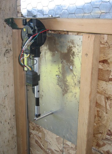
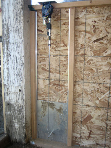
Here is the automatic door I built with an automatic car antenna (click the image to see it in action). I chose the antenna method because it has a built in stop when it reaches its end in both directions. This eliminates the need of more circuitry to control “run timeâ€.
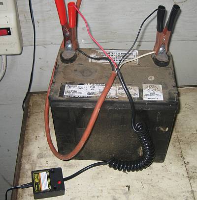
Mine runs off a little 12v lawn tractor battery. The battery is kept up to charge with a “float†charger. The door opens and closes with a photo light sensor. The reason for the battery is so that a power failure will not cause a problem. The reason for the light sensor is so that the length of daylight does not need to be constantly adjusted on a timer. BUT, you can simplify things and use an ordinary appliance timer plugged into an AC outlet, and then use a 12v DC power supply to power the antenna.
This is just one way to use an automatic car antenna. With some imagination you could probably come up with many more designs.
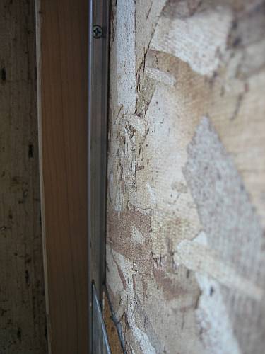
As you can see the antenna is mounted upside down. The door is made from an 1\8″ ALUMINUM panel. It is light in weight but very strong. The door channels are 1/4″. I have a 3″ spacer connected to the tip of the antenna to the door. You can measure the distance you need to determine the spacing length. I used a piece of aluminum stock and tapped each side to mount it. The side on the antenna tip has a hole for the tip to set in, and then I used the tapped hole as a “set screw†to keep the tip in place. I have my tip connected towards the bottom of the door. This makes the length of the door channel a bit shorter in order to match the up and down stroke of the antenna.
Be sure to carefully measure the lengths and travel distances needed for the antenna to move up and down freely. I have heard of some discussion that the travel distance does not need to be exact because the antenna’s “auto stop†feature will sense the end travel and the motor will time out. But that will be up to you.
If you do not have some aluminum sheeting lying around, you can find some at Lowe’s or etc. Aluminum can be easily cut with your skill saw. Just make sure you have a carbide blade and wear safety goggles. Even some type of plastic sheet would work. Just keep it light and strong.
The door channels can be purchased also at Lowe’s or Home Depot.
The best price for the antenna was on-line at Beachaudio.com, but they may be out of stock. Just search the web for the least expensive “automatic antennaâ€. Mine was about $35.00. The antenna MUST only have three wires. (Beware of the non automatic antennas that require the user to “toggle†the antenna up and down manually). Two wires connect directly to your power source. The other wire that is not black or red, is the “up down†trigger. That is the wire that you connect to the timer or sensor circuit.
If you go with the 12V battery, the float charger can be bought at Harbor Freight Tools for under $10.00.
I have updated this article to mention that the there may be a better control system other than the night/daylight sensor that is described below. I have used this sensor for about a year. However, just recently I noticed that the control unit was sometimes “confused†in the mornings and would make the antenna move up and down erratically. Not fun for the chickens. It was mainly due to setting the photocell too sensitive in order to stay open at night as long as possible. Please be sure to read the later posts regarding an Intermatic ST01C timer. This timer is very unique because it does not rely on household current to operate. It is also very unique because it has an “astronomical†feature which updates the internal clock when dusk and dawn occurs in your region. It is powered by a 2 year lithium battery. Below is the night/daylight photocell circuit, if you decide to want to experiment with it.
Here is the circuit. Its pretty simple and self explanatory and would require someone that has done a little soldering in the past.
The only thing that is really not explained is the CDS photocell. One could try different types to see which works best. The one I ended up using was from a photocell variety package purchased from Radio Shack.
If you decide to go with the photocell circuit, the antenna’s power wires (red and black) must be always connected to the 12vdc power source and not be controlled by the photocell circuit.
A few thumbnails you can click on for the control box, door channel, battery / charger, photocell
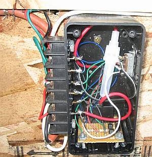
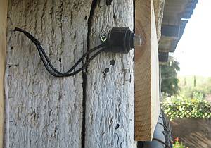
On the other side of the box I have a little slider switch that makes the door close manually.
The tip spacer/connector will probably be the hardest part for a lot of people to figure out to. There plenty of ways to get that done. I had a piece of an aluminum rod that was solid. I drilled and tapped each side of it. There is a screw going through the outside of the door to one side of the rod. I drilled a hole in the rod for the antenna tip to sit in. The screw on that side of the rod is a set screw that keeps the tip in place.
(Rob Note: A huge thanks to Bob for this great design, pics and wrtieup and for letting me post it on the site. I know we are both looking forward to reading some of your comments!)
I live in Georgia….do you install? I think you idea is the best for the money…but why not let the nylon strap push -pull the door? it would eliminate the metal antenna
Bravo-bravo!!Will not the adjustable part of a cheap outdoor flood light, motion detector work??? Have to give it some thought…..
Thank you for the complement.
You can come up with just about any idea with this.
Yes, Kevin. Good idea. That should work. I was to scared to do it. I didn’t want to break anything. But if you use it on a door like mine, you may need to add a little weight to the door if it was not heavy enough to help the cord come out.
On the motion flood light, I can’t think of a simple way to separate the photocell cell unit from the motion. This is all one circuit. But, not a bad idea in general. Maybe Home Depot or Lowe’s has an inexpensive indoor or outdoor 120V night light? Then you could plug the 12VDC power supply (transformer) into the light socket.
Bob
Is the point of the door to protect the chickens from night-time preditors? Is it safe to assume that the chickens will be inside the coop by dark and will not be stuck outside? Is it reasonably safe to give chickes free run of a pasture with access to the coop with this type of automatic door? THANKS!
Hi Lance,
Yes, that’s the whole idea. Many of us have a problem with some type of predator trying to snatch our birds at night. I found out the hard way once that raccoons are a problem and time to time there are foxes too here.
I was able to get mine to close just about at full dark. But I need to see how it does on a bright full moon. The key is using the correct photocell so that the unit’s adjustable control will be within range. I found a perfect one. It was in the Radio Shack’s 5 pack photocell package. Anyway, I can explain later how to find the correct cell to those wanting to build the photocell circuit.
Bob
Brilliant. Simply brilliant. In the process of preparing a coop for chickens now and was already noodling a solution when I googled and found your post. Did I mention you’re brilliant? Pulling my parts list together now…
Thanks for sharing your project! Doug, Nashville, TN
And…in deciphering your electrical diagram, am I correct that the 1k and 10k notations are inline resisters? And the “50k trim pot”…what is that? Please feel free to email me to discuss offline at kimdug@yahoo.com. Thanks again!
I assume the 50k pot is similar to this http://www.radioshack.com/product/index.jsp?productId=2062355 from radioshack.
I am not terribly familiar with wiring schematics, where does the B terminal off of Q1 goto?
Thanks,
Dan
Hi Doug,
I did email you a few days ago but I have not heard back. Hope your project is going well.
Bob
Hi Dan,
The “50K-Ohm Linear-Taper Potentiometer” will work fine but its a little big in size. You can use a small “trimmer” type that adjusts with a small screw driver instead. Just drill a hole in your project box for access. Here is the one I use: http://www.jameco.com/webapp/wcs/stores/servlet/ProductDisplay?langId=-1&storeId=10001&catalogId=10001&productId=254028&
The B terminal (base) of the transistor also goes to the 50K trimmer. The trimmer (potentiometer) has 3 legs. The leg that is the most “middle” of the trimmer is called the “wiper”. It goes to the base of the Q1. Whenever you see a resistor symbol with an arrow pointing to the center, that is a potentiometer.
By the way, here is the photocell that I also recommend. http://www.jameco.com/webapp/wcs/stores/servlet/ProductDisplay?langId=-1&storeId=10001&catalogId=10001&productId=120301&
If you need help, feel free to email me direct at galaxyflyer1@yahoo.com
But check my next post for more info!
OK everyone,
I did some searching for a “dark activated switch” that works on 12 volts. I found one here.
http://www.bakatronics.com/shop/item.aspx?itemid=377
I have not tried it but it sure sounds like it will work. It’s only $6.99 for a kit and $3.99 more fully assembled! This is the way to go. Because the photocell is mounted on the PC board, you would need to make sure it gets enough light without subjecting the board to weather. I would dis-mount the cell and extend it to a desired location.
Bob,
I have a question for you. I came across this article here http://www.buildeazy.com/photo-chicken-coop-beatarticle.html for an automatic door opener that would both open and close the door using a curtain opener. I have the parts available after scrounging around the house, so in terms of cost it would be cheaper for me to this route rather then the antenna route (which is brilliant!)
The thing I don’t like about the curtain opener setup is that it’s not automated to dusk/dawn activation. I’m not technical, electrical, or what-have-you minded, so I thought maybe you would know.
Do you think that this curtain opener setup could be adapted to using photovoltaics?
If someone would come up with a way to have it activated with daylight, nighttime, that would be even better.
Thanks.
Hi Vadgo,
I did find that site a while back when I was looking too. Good idea but the cost of the drapery motor is what made me look further. So I can’t really comment on the device. But if you have one and enough parts, go for it!
As far as using the light sensing kit for other applications? Yes you can. The sensing unit has a relay that allows you to switch whatever you want on and off. So you can run one leg of a 12 volt or 120 volt device through it’s relay’s contacts (Just like a light switch). As long as you do not exceed the current capability of the relay’s contacts. You should be fine with what we are dealing with.
Good luck!
Bob
OH, You will need a 12 volt DC power source for the light sensing unit. But just to power the unit alone will require a very small (low current rating) transformer. Here is one as an example that will work fine. You may have one laying around too.
http://www.jameco.com/webapp/wcs/stores/servlet/ProductDisplay?langId=-1&storeId=10001&catalogId=10001&productId=305103&
I can’t believe it! I’v made the door that Vadog is talking about. I made it about 2 years ago. It has worked flawlessly. I have even made a DIY DVD on how to build the door. Mine is set up a little diffrent…a little more compacted.
I guess great minds think alike.
E-bay has some cheap antennas, so would a local boneyard.
What about the light sensitive controllers I saw at Lowes the other day? I am guessing I would need some sort of relay? Maybe use a latching relay?
I also saw a timer, what was rated 120 vt and was programable for the seasons/ daylight savings…Maybe use that instead of photocell and simplify the system? The timer was less than $10.
Do these antenna have some sort of limiter or relay inside them that allows them only to run till they go up or down and then shut themselves off? Must be…Sort of like the self park on wipers?
Hi Bavak,
Yes, as stated in my article, automatic car antennas have a built in duration limiter. That is the main reason for choosing this simple method.
If you choose to go with a 120V system, you can simplify things and eliminate a need for a relay. Use two 12 VDC power packs instead.
Use this type for the antenna’s “trigger” plugged into the 120V timer. Meaning that it takes little current (amps) for the trigger.
http://www.allelectronics.com/make-a-store/item/DCTX-120/12VDC-200-MA-WALL-TRANSFORMER/-/1.html
Use this type constantly connected to the antenna’s positive and negative leads. Meaning that you need at least 3 amps for the antenna’s motor.
http://www.allelectronics.com/make-a-store/item/PS-1263/12VDC-3.5A-SWITCHING-POWER-SUPPLY-BLEMS/1.html
If you choose this method, make sure you get your polarity (+ and -)correct. Simply tie both sides of the transformer’s negative wires together. All this is easier than it sounds!.
Good luck,
Bob
The car antenna is a great Idea, BUT what about durability. I have had cars with power antennas and sooner or later they failed. And all the wiring seems over whelming for the average person.
I build a automatic coop door about two years ago and it has worked flawlessly. As far as the electronics it’s basically plug-in-play. It has opened and closed everyday for almost 2 years without a single problem. It door operates from a timer; I want to control when it closes and when it opens and not worry about dark clouds going by.
Go with what works best for you.
I remember a saying when I was a Kid.
There is more than one way to skin a cat.
I have also seen auto antenna’s fail. However, needing a 1st time replacement a year ago on a 1988 Chrysler is well understandable. Any electronic device will
fail some time or another. Even a “plug and play timer”.Maybe after a few years of use, one should replace the antenna with a new one for maintenance? Also, cloud cover will not close the door if you set the control at night right before pitch dark.
“Over whelming for the average person”
If you eliminate the daylight controller and use a timer as described previously, it would be much simpler for someone that is not “electronic project savvy” to build. However, the purpose for this article are for those that want a DIY project. If one does not understand how to connect 3 wires on the auto antenna, then I agree that they should have reservations form building this project.
Myself and others are (were) searching for something. I could not find anything except for a costly one to build or a costly one to purchase.This is just my design that works for me and that I wish to share with others that are interested. It would be nice to see more ideas on the web to choose from. Where do I (we) find your design?
Would you please share your device with us? I’m sure that more ideas other than my auto antenna would be greatly appreciated by everyone.
Thanks,
Bob
Hi Bob, I know you and I have lost sleep thinking about how to come up with the doors that we have. Your door has a great advantage over mine because it doesn’t need to be tethered to the house for electricity.
Yeah, If a person can’t connect 3 wires then may by they should stick with opening the coop by hand.
Bob, my door is similar to the door that has a link on one of the comments, using a drapery motor. I know the motor is a little pricey. I bought my almost 2 years ago it was less than $75 then, it’s now like $79.
When I built my door I started videoing it. I sat on the DVD idea for a year. My friends and neighbors were so impressed with the door they encouraged me to complete the DVD.
I now have a DIY DVD, it’s basically free…I’m charging $10, shipping and handling included. That’s why as they say “I’m keeping my cards close to my vest.” Both my wife and myself has had our hours cut at work. I not trying to get rich just trying to break even.
I figured with a DVD, a person watch if over and over and watch it while they are building it to kinda hold there hand so to speak.
Hey Bob, I just responded to your email. I missed it in the junk mail folder. Still compiling parts for the project… 🙂
Ok I have been reading all the above and will be building something similar. I have absolutely no electronic aptitude but feel I could build what you have outlined. I think instead of a guillotine door I will just adapt it to a man door. I plan to use a timer. I’ll reset it as the light changes. The main thing is I get up to go to work at 3:15 AM and don’t have the time to stay up till 9:30 PM for the chckens to go to roost (last night I was seriuosly considering turning my laying hens into fryers). That being said how would I adapt a 120V timer to a 12VDC circuit?
Hi Kevin,
Above on post 17, I give examples of 2 transformers that you will need and explain how to wire them. If you would like, I can draw a picture and email it to you. My email is galaxyflyer1@yahoo.com
This is absolutely great!!! I stopped by the junk yard today and the first place told me $50 and the second I looked a bit more pitiful, explained what I wanted it for and got one for $15. Now, slight problem. I am going trying to put this together on the quick as we leave town next week. So, I have a timer that is for a deer feeder that will take a 12V input, and pass the battery juice though it when open. How do I interject this into the circuit so that I can reverse the polarity headed to the motor and get the antenna to retract? It is probably simple, but I appreciate the help. Oh, one last thing, If I actually make mine work, can I take the credit for it with my wife kids and friends? 🙂
Hi Mark,
The power antenna does not retract with reverse voltage. When the trigger wire has 12V+ it pushes the antenna out. When the 12V+ is no more present on the trigger wire, the antenna retracts. The trigger does not pull any current to be concerned about. It just senses that the power has been turned on or off. Meaning you do not need to worry about the unit pulling constant voltage and wearing down your battery. The only time there is current draw is when the motor is moving. Remember to have the red and black leads of the antenna ALWAYS connected to a constant 12DC supply. The timer only should control the trigger wire.
Now, back to your deer feeder. I’m not sure that it will work. Can the feeder supply you voltage for the entire day or night interval? (Just like a lamp timer) I think feeders only give a “burst” of voltage to the unit to dump the food. Not sure though.
Good luck. Let me know if I can help some more. Be my guest and let your family know that it was your idea 🙂 Watch them in ah when you demonstarte it.
Bob
Thanks Bob, I actually purchased a used antenna from a salvage yard, and it only had two terminals. You were right about the deer feeder timer, the ones I had do not run for longer than a couple of minutes. So, here is what I did. I had to go to 110 to get a timer, and ran power to the coop. I then plugged in a 12V adapter into the power directly. I also plugged a timer into the power, and a second adapter into the timer. I bought a DPDT relay from Radio Shack, #275-206 and plugged the timed powersupply into the activator side of the relay, and the constant hot adapter into the one side of each swith leg on the relay. I then took the two sections of the opposing switch legs and cross wired them so that when the relay was active, power flowed one way, and when dead, it flowed the other, and plugged those into the antenna.
Well, through all of the testing it worked great. I installed it this afternoon, went open just fine, but at 9:15 tonight, it did not close. I found the power supply that powers the motor was dead. So, I grabbed another power supply, closed the thing and will work on it more tomorrow night. I may attach a different timer that has two power plugs and set it up so that the power supplies are only active for a few minutes each day. Oh, BTW, I used an acrylic cutting board for my chicken door, $5 at harbor freight, a carriage bolt and an old grounding rod sliding connector to put it all together as I did not have the tap and die set easily… I think the back of my neck is getting sun burned.
Anyway, I am not taking credit for it just yet.
Hi Mark, I don’t understand why you need a relay when using two seperate pwr packs. How does the power antenna work with only 2 wires? Does it not have a trigger wire or does it just open and close when 12v is applied? Maybe the antenna you got requires a relay because of that. But if that’s the case, still with 2 power packs, you should not need a relay? Please explain..
Thanks,
Bob
Well, the antenna I purchased works by pushing out the antenna when power flows one way through the two connectors, and pulls it back in when it is connected the opposite way. So, I needed a way to tell the power to flow + to – in the morning, and – to + in the evening. I did this with a timer, and eventually 2, plus a DPDT relay. When the relay is active, the switch flows power from a power supply to 2 terminals. When the relay is not active, it flows it to two different terminals. I simply crossed the terminals so that the opposite terminals went to the same connection on the antenna and then when the relay is active, the power flows one way and when not, it flows the other. I had the second power supply running off the timer so that the relay is activated off of a 12V power source, but only active during the day. I decided to add an additional timer to reduce heat and so, I have one timer that activates the relay in the morning from 7 – 8 AM, and the second that powers the antenna from 7:15 – 7:16 AM and again from 9:15 – 9:16 PM. That way, the relay is active at the 7:15 slot so the power pulls the antenna up, and the relay is not active so the power pushes the door down. I was pressed for time, but your solution would have been cheaper and easier in the long run for sure. I plan on converting the system when I get back from a trip we are taking to a simple controller circuit that can run off of battery similar to yours. Don’t worrk, I have someone coming to let the chickens in and out while we are gone, but hopefully this will help things a bit. (If it keeps working)
Does that make sence? I needed the relay because I could not easily avoid the potential of both power packs being on at the same time when I was in a single timer solution. I suppose now that I am at 2 timers, I could have done it without, but I hoped to keep it on the cheap. Oh well, my cheap projects usually cost more in the long run but boy are they fun during the ride.
Thanks again!
OK Mark, I see what you are up against. Sorry for all the questions but I’m sure that our posts will help someone else who runs into a similar issue. I don’t understand what you mean about a heat issue?
I think a power antenna with 3 wires would be much simpler. But you have yours already and found a way to make it work 🙂 I’m assuming that the antenna has a built in limit switch? Meaning that when it reaches its end travel (up or down) the motor stops’ running even when power is still applied? Then starts running the opposite direction when power is reversed? (then stops) If so, I just drew out a way to wire one relay and two 12vDC power pack to work with one timer. Or just 0ne 12V pack if you use a 110 VAC DPDT relay instead. This will give the antenna leads + – when on and – + when off too (or visa versa). I know you are going to leave soon, but I can explain later or draw it up. But it seems that you already have a good grasp on things! You can email direct if you want. My address is on a few posts back.
Bob
Thanks Bob, My design is too complex for sure. You are correct, the antenna has a limit switch in it and does stop on it’s own. The heat issue refers to the fact that one power supply stopped working the first day I had it installed. Our coop gets pretty hot here in the south, add that to the heat of the pack and box that it sits in and it gets pretty hot. So, I wanted to turn off the packs as much as possible to avoid heat. The timers I got were from lowes and seem to have intermitten function problems. They always run, but not according to the programming. Can’t explain it, but when I cycle through the auto manual off settings and back to manual it begins working again. Too much complexity. I agree, let’s keep it up until we have many options for people to learn from.
Oh my! My teenage stepson bought me a new power antenna, excited about helping me to install your automatic door. It only has two wires. After reading the give and take between you and Mark I don’t know that we’re up to the challenge. I thought getting it to work on a timer was going to be easy. Can you reduce the wiring instructions for a two wire with timer connection to its simpliest form? We know nothing about resistors, relays, etc.
Hi Duane,
It looks like you also stumbled onto a 2 wire antenna. I have a thought that may work. First, test the antenna to see if it still HOLDS open or closed when you disconnect the voltage. In other words, try this:
1. Apply 12vdc to the antenna to make it open. Then remove the voltage. Does it stay open or does it go back in? If it stays open, go to step 2.
2. Re-apply the voltage the same way. Does it still stay open or does it close now? If it still stays open, re-apply the voltage the opposite way (reverse the polarity). Now it should close.
Please give me your results and I may be able to come up with a way for you to do this without a relay.
Bob
Yes you have to completely switch the wires for it to go down. It goes up. stops, and to bring it back down, you have to reverse the polarity. I dont know what to do.
OK, I would assume then that it stays open even if you remove the the wires and will NOT go down after you remove the voltage indefinitly? (stays stuck open). If that is the case, let me do some bench testing for you before I tell you what to get.
Bob
Yes, it stays open when you remove the wires.
You will need two appliance/lamp timers and two 12VDC voltage sources that will plug into your timers. This will eliminate the need for a relay.
The 12VDC power sources need to have enough amps to move the antenna. About 1-2 amps (1000 MA – 2000 MA) minimum or so. Just test it and see. Not sure what you are using to test with (maybe your car battery?) But batteries are not an option with this project anyway. Here is an example of what would work (x2)
http://www.allelectronics.com/make-a-store/item/PS-1256/12VDC-1.5A-SWITCHING-POWER-SUPPLY/1.html
First let’s set up the power sources. Connect one power source to the antenna, power it up and make it move out. Then unplug that power source, but do not disconnect the wires to the antenna. Now connect the other power source to the antenna the opposite way (reverse polarity) right on top with the other wires. Now plug that power source in. The antenna should move back in. Then unplug that power source.
So now you have one power source that moves the antenna out, and one that brings it back in when you plug each source in ONE AT A TIME BY ITSELF.
Now set one timer for the morning open time and the other timer for night close time. But have each timer’s “off†peg set so that the timer is on for the shortest amount of time possible. Probably 15 min or so. That way the 12V power source on each timer will not stay on the whole time.
That should do it. It’s easier than it sounds!
Let me know how you are doing.
Bob
Bob can you give more detailon how you connected the antenna to the door?
Thanks
OK so there’s about a zillion posts with several brllliant people working on designs for door opening and closing devices. I am overwhelmed! But glad this is still going on.
If any of you decides to build and market a device that’s reasonably priced, I’ll be first in line! Let me know because I’d really like to do this for the safety of my chooks!
BTW this could be a real money maker, since the backyard chicken hobby is BOOMING and growing by leaps and bounds!
Sue
Yep, I am a very bad business man. Others that I know would have put this in production by now. I’m sure it will happen soon. Maybe I would get lucky and a cut or at least make me an employee 🙂 I tell you, if there is a big want for this, I could put together a complete product. But because of lack of mass producition, the time to build and parts may end up close to $200.00 or so. I think that must folks here want to try a “do it yourself” to save money. I thought I saw one for sale?
Mike, I attached the tip of the antenna to a solid piece of rod. The rod is a bit larger in diameter the antenna’s tip. Therefore I was able to drill a hole into the rod just big enough for the tip to sit in. Then I tapped a hole at the end of the rod so that I could screw in a “set screw” to hold the tip in place. The opposite end of the rod has a tapped hole so that I was able to screw the door to the rod.
I’m sure you could even do something similar with a piece wood too. Or, forget what I did and just tie a string to the antenna’s tip and to the door, and let the door’s weight drop the door as the antenna comes out.
Just use your imagination!
Has anyone done this with solar power to charge the battery? If so, how did that work out?
Hi Kit,
Since you are only drawing power from the battery when the antenna is in motion, a solar panel should do a fine job of keeping the battery up. I did not use a panel because I have 120AC at the barn so a simple float/charger works for me. Whatever panel you decide to use, make sure to periodically check the voltage on the battery to make sure it is kept up. Since the antenna will only run 2x a day, I bet a fully charged battery will run many days without needing any attention anyway.
Bob
Hi Bob,
I can’t figure out those three wires, but I can learn! I have red and black wires that have tubular attachments on their ends like yours and a black wire that has a u-shaped attachment, which I thought was to ground? How do I tell which one is the trigger wire? Please explain why the two non-trigger wires have to be continuously hooked to power. I cut the end off a “12v 500ma” adapter I had laying around, and it only registered 9v on a battery tester and did nothing to move the antenna…maybe because I don’t have the trigger wire set up? When I get the trigger wire right, if the adapter I cut up doesn’t power it, can I use a 14v 700ma adapter or will I burn up the antenna? Thanks for your help!
Hi Paula,
I guess the antenna factory was too cheap to color the trigger wire a different color 🙂
I don’t think that 9 volts will make it move. But the 14V at 700ma may work. 14 volts will not be a problem. A car battery reads close to that or sometimes more when the car is running due to the output of the alternator. It’s just that the 700ma may be a bit low, but it will not hurt to try! But make sure it is a DC supply and find the polarity with your volt meter.
Here is how the manufactures designed a 3 wire power antenna; the positive and ground wires need to have power always. When the antenna’s circuit senses that there is voltage on the trigger wire, it will tell the motor to run. When the circuit senses that the trigger voltage is gone, the motor needs to run again. Therefore the motor needs to be ready to make a move depending on what the trigger circuit sees. The great thing about this is that the trigger takes VERY little current. Much less than switching the main power on and off for the antenna. So it saves ware and tear (current drawing) on the radios on off switch or our chicken switch!
Look at all three wires. You say that one is red so we know that it goes to the positive side of the power source. Here is my next guess. The black one with the tubular connecter is the trigger wire because the black one with the u shape is a “grounding lug”. Put the u shape wire on the negative side of the power source.
Now you will have the red and u shaped connector wire connected to the 14V DC power pack. Plug it in. Now touch the other black wire (trigger wire) to the POSITVE side of the power source and the antenna should move. If so, you would leave the trigger wire always connected until you want the antenna to come down. When the antenna runs, you will notice that it will sound like it is still running at its end for a few seconds. This is normal. It is finishing its cycle and then telling the motor to stop.
Let me know how you did.
Bob
Hi Super Bob!
Thanks. It worked just the way you said. It goes up and down very slowly, though!! I hope this doesn’t mean it will not have enough power to lift the door! I will hopefully be putting it together this week. Thanks so much for your help. By the way, as far as a business, you may already know, and it may be too much work, but I see sites called “hubs” where people simply give information and advertisers pay to advertise? Maybe that could work out for you. Any advertiser could see that your information draws a lot of business. Best to you, Bob, and thanks again.
Paula
Cool! Im glad it worked for you Paula.
Just for the heck of it, ckeck the voltage accross the power leads as the motor is moving to see how much the voltage drops. If it drops below 10 volts, you should probably upgrade to a heavier (more ma) power source.
BTW, what will be controling the open and close times?
Bob
Bob
I am working on a simular project but Iam going to use a rear window motor off of a 86 ford bronco and the frame. I am using an dpdt relay because of reversing the polarity and for limit switches I am using door light switches for top and bottom .now the only thing I am sure about is your wiring schematic I bought all the items and I am trying to follow it I am not real familar with elictronics but I do have knowledge of electric. Iwas looking at your drawing and I cannot determine the path the electric is taking. to me it looks like the positive side leaves the battery splits for the contacts continues to the coil side of the relay were it splits again from there it continues on to be split to go to transistor Q2 from there it continues onto a 1K resistor and then on to the photo cell after it comes back out the other wire of the photo cell it goes to the poteneometer goes out the center leg of the pot into B side of Q1 transister if I am on the correct path to this point if not coud you put me on the rite path also it looks like both E legs of the transistors and one leg of the pot is grounded also is the C leg of Q2 going to the Neg side of the coil and if so am I also correct there is a diode between the positive and neg posts of the coil like I said I am not real familar with electronics so could you please explain. By the way your idea of using a antena is great I would have done the same except I had every thing else laying around the house
Bob,
In #17 above, you say: “If you choose this method, make sure you get your polarity (+ and -)correct. Simply tie both sides of the transformer’s negative wires together.” Should this read tranformers’ rather than “transformer’s”? Not to be a grammar snob, but I think the former is what you meant, in that the negative wires from both transformers be tied together. But, if I am incorrect, I have a question: what do I do with the negative wire from the power supply that powers the “trigger” wire?
Hi Philip,
Yes, you are correct. Tie the negitive from both transformers together. This makes a “common ground”. I can see how my wording could have been confusing.
Good luck!
I need one of these contraptions so badly…I do not have the brain or confidence to do this, tho. Is there a complete materials list that I can use to ‘go shopping’ ? I would want to plug it into a heavy duty extension cord tho, I don’t want to recharge batteries…winter is bad enough without lugging a heavy battery around. oh yeah…and who is available to help ? lol
oh, one more thing… timers. I have a photo timer meant for outdoor christmas lights, would that work or is the other kind better?
Bob I have an antenna that will power up using a 12V battery extends and retracts when reversed. my problem is when I use a 22V output transformer charger it will not fuction at all but when I use a 9.4 it will extend about 2 inches and stop, but when wires are reversed it will not retract.
do I have to have special type of 12V transformers or am I missing something here, I really need your help figureing this out. as I am not electrical savy
Rodney
Bob
In # 36 you explained that you can put the wires opposite voltage toghter so it will extend then retract at different times as needed, but my antenna wont do that and my 12V power sources work ok sometimes and not other times any sujestions
Hi Rodney,
First let’s let the readers know that you do not have an antenna with a trigger wire, but one that has only 2 wires that require a polarity reversal when needing to retract it. Like in post 36.
For your antenna, your power sources both need to be 12-15V DC at no less than 1 Amp (1000MA). The more the better. Unless your antenna is just a current hog:) If you have a volt meter to attach while the antenna moves, check for voltage drop. You should be able to connect one source up to the antenna one way, and connect the other source to the antenna the other way (cross polarity). Usually this should NEVER be done, but because you are only turning one source on, ONE AT A TIME, it should control the antenna up and down. I did not know if this would actually work, but I did a test on my bench with two power packs and it worked for me. If everything I mentioned is how you are doing it, then maybe there’s something different with your sources compared to mine. You would then need to go with a relay, which is not that difficult to do.
Keep me posted.
Bob
Bob,
Let me start over, The type of antenna is a automatic universal type, it has 2 wires, red and yellow, plus there is a switch wire that could be connected to both of these wires, I think which would be used for manual operation. which will not be needed. I took the to power wires and connected them to a 12v battery red + yellow – , the ant extended, I reversed the two wires, it retracted.
I then tested it using a 12v 3amp power supply and it extended and retracted, then I connected two power supplies in reverse on top of each other plugged in one for it to extend and it extened, un-plugged it and plugged in the one for retracting and it did not retract, I had to use the 12v battery again to make it retract, why is this?
I should be-able to piggyback the wires in reverse since you are using two different power supplies, one supply for up and the other for down at two different times, with two 110 timers.
Now when I reconnect the extending 12v power supply the ant will not extend at all, BUT connecting the wires to the battery it will work like it should.
What might be my problem.
Rodney
Bob
I did some more testing and found that when the ant has stopped it still draws current when it is connected,both ways, it also looks as if I fried the 12v transformers they show zero on the voltage when connected. there is a large draw down when the ant operates so maybe a relay is what I need to stop the current and fix my problem.
If so please explain the procedure for me.
Rodney
Rodney,
It sounds like the 12V transformer maybe defective now. Not sure why, but my biggest concern is why does the antenna still pull current at it’s end of motion? How did you measure the current draw? Perhaps it is a minuet amount. To be honest, I really don’t like the way about going with your type of antenna. I was just trying to help come up with a simple solution for someone previously who had a 2 wire antenna laying around. My power crossing test worked, but it may not be a good idea on certain types of supplies that I have not tested on.
I really think that you would have a lot more luck with an antenna that has 3 wires. I just purchased a second one like that for a spare. I bought it from a “buy it now” company on eBay. Just as an example;
http://cgi.ebay.com/ebaymotors/ws/eBayISAPI.dll?ViewItem&item=220477622560&category=33639&_trksid=p4340.m263&_trkparms=algo%3DSI%26its%3DI%26itu%3DUCI%26otn%3D10%26ps%3D63
Mine was $16.00, this one is $23.00 When buying an antenna, look carefully at the picture. YOu should see 3 different colored wires.
You would still need one timer, one 12VDC low current supply and one 12VDC higher current supply like the one you had. This time you would not need to cross them and they would basically be isolated from each other except for the “common ground” like in post# 17 and 47.
Oh ya,
With your antenna you can use one 12VDC source and a 12V DPDT relay along with your timer.But you need to come up with a working 12 volt source that will move the antenna with no problem.
Let me know if you choose this route. What I can do is draw up a diagram using a Radio Shack relay on the photo bucket web site to link to for all to see. Unless I can put an HTML code here?
Bob
Bob
when i check for current draw i just put a volt meter on the battery and watched the draw down continue after the ant had stopped no matter which way it was going.
Anyway why dont you draw up the diagram that you are talking about, couldn’t I can use a 12volt battery with a small solar panel which would keep it charged.
I really want to beable to use what I have instead of buying another one at this time.
Rodney
Sure, a battery with a panel will be fine. Just check the voltage every now and then to make sure it is kept charged. I will start on the diagram for you.
(Bob, I got the image to work – Rob)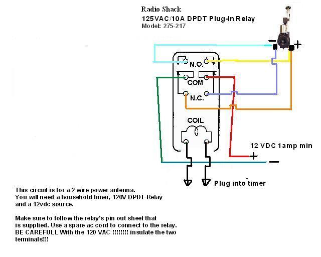
Thanks Rob!
Hope you are doing well..
I’m still waiting for my paycheck 🙂
I made one of these , but used a Intermatic timer model ST01C. Cut off or fold back the red and the green wire they are not used. The black wire is the load , the blue wire goes to the trigger switch, you have to reverse the timer in programing or the timer will trigger the door to open at nite and close in the morning, Intermatic has a telephone support that will walk you thru that . The timer is powered by a lithium 3 volt camera battery that they say will last 3 years or more . If you do have to change the battery, they said the programing remains, you may have to set the time of day as in current time back up. I also used a 12 volt deep cyle battery to power the antenna . I use a solar charger on it to keep the battery charged . Timer cost 30$
antenna cost 5$ , tracks for door 10$ , cutting board for door ( harbor frieght) , there was 2 in the pack the thicker one actually fits the tracks very well.
assorted other stuff 20$ ( screws , nuts, PC-11 epoxy )
Hey Chris,
That’s a great simple idea! I looked up the timer and I see that it does not need 120VAC, just the 3 volt battery to operate like you said. So any voltage can be switched. That is way better then an appliance timer circuit because you would need a relay and two seperate power sources.
I hope others read this post. It sure is a big help for those that do not want to mess with the photocell circuit. BUT remember everyone, you need to use a power antenna that has THREE wires (a trigger wire).
BTW Chris, did you get the antenna idea from here, or did you find it elsewhere first?
Thanks,
Bob
I got that from here, and looked at it and thought,…, hmm must be a simpler way.the only concern I have is, the chance of a bird getting caught in the door…the antenna i got you can not stop , it would most certainly kill a bird, the red wire from what I can tell could be used to trigger voltage to a relay? perhaps a relay that went to a small sensor so if something was in the door it would stop it? just a idea…I also liked the cutting board door better, it slides very easy, and the alum channel that is found in most hardware stores in that standard selection of channel, angles and flats that is a display, set in most hardware stores, that channel fits the board perfectly, and because it is like a skid , it will never stick.
The only caution was the temp range of the switch at about 20 deg it could start sticking they said. So an area that was well above that would be best to mount the switch in. Also they said to keep a eye open for a CT-1000, they are bringing them back into production again..
Oh the coolest feature of this timer was the astro feature, it ajusted automatically to the difference in the daylight hours during the seasons so it will allways close at a hour after dark , regardless of the time of year 9or what ever time you set it to after dark,) same for the other end , changes the open time as well…
Wow, that is really cool!
Seeing that it replaces a wall lamp switch, I would have never thought that it would have a “daylight difference” sensor. That’s one reason why I wanted to stay away from a regular house timer. Allways touching up the time to day light length. The other reason is because of a 120V power failure. Looks like this thing covers these two concerns.
I know the antenna can be quite powerfull, but I think they move slow enough that it would give the bird enough time to get out of the way. Unless they sleep under it. Opening would never be a problem. And if it closes when it’s just at full dark, all the birds would be in.
Thanks Chris for sharing,
Bob
Bob
Looks like the relay works, but there seems to be one small problem, I followed the diagram as it indicated, the door will open and close like it should at the desinated times but for some reason the motor stays running until you disconnet the power, then you can reconnect the power and when the door works again the motor once again keeps running when the door stops.
I thought that the relay would switch off the power, but looks as if it is not doing that.
Any sujestions?
Regards,
Rodney
Hey Rodney,
I’m happy you got the relay circiut built! It sounds like you built the circuit correct. The relay cannot shut down the voltage that it is sending. It does not know how long to send voltage. It is only a relay. As you see, it can only send + – or – +. It sounds like your antenna does not have a “duration shut off” like most power anntenas.
I can’t believe that someone designed a power antenna without a duration circuit built inside. I know you said it came with an on/off switch. It looks like they want the user to sit there and watch the antenna come out and turn it off manually. I do not know anyone that moves their antenna in their car up or down with a seperate switch in their car. With the antenna that you have, you would need to design sensing circuits at the door that would tell other circuits to stop the movement.
You see, that is the whole reason why I chose a STANDARD power antenna that is controlled by the radio being on or off. Because at it’s end point (in or out), it runs for a second then knows that it should stop moving until the voltage changes again. It’s built in the antenna.
Rodney, I’m sorry but I can’t help you continue. You would need more sensors and circuitry to get that type of antenna to work. You would be WAY better off bitting the bullet and find one with a trigger wire (3 wires total) You can find them on the internet between $15.00 to $35.00. Depending how much you search to find a deal.
Don’t give up! It’s well worth having this system.
Bob
Chris,
Do you have a picture of your setup?
I will get some pics together in a few days, it was really quite simple to build , perhaps i will find a host pic site and link them , or i will figure out how to host them off my site.
I had originally planned on building the drapery motor door, but now I like Chris’ setup better. So I’ve bought the Intermatic ST01C like Chris’ and now I’m off to the junk yard to search for an antenna. Are there a few car models that you would advise to get an antenna from? Also, I’d like to run the antenna in Chris’ setup from the coop power outlet since I don’t want to mess with batteries and charging. How would that be done?
Thanks.
Bob hope it is ok for me to answer this ………
Vadgo..
You could get a inverter that powers 12 volt, be aware, the antenna’s draw about 4 to 5 amps , also you need a 3 wire antenna , you can sourse a antenna that is 3 wire form Ebay for about 35$ or less . what you have in the wiring of that antenna is a red wire (+) or hot a black wire (-) or ground, and a trigger wire blue that triggers the antenna to go up or down accordingly, also, the intermatic timer is preset for the factory normally to be in the right configuration for the off on with the relay set up, mine was the exception. The color codes could be different in a different model antenna of the wiring , but they process the current in the same manner, or would have the same schematics . ( Hopefully I will be able to get the pics of the project uploaded today).
This is the only 3 wire antenna I could find on ebay. this is a Ebay Store as well,
so, I would assume that this link would be good for a while ,
If not here is a direct store link for future.
I have no affiliation with this seller what so ever…….Just trying to help those that may not be familiar with the ebay stores search option..
Greeting from Stevens Point, WI. Right in the middle.
I am looking for the companion invention…The machine that automatically empties my trap of live and very angry coons! My children think they are cute until they get close. I am up to about a dozen. My neighbor got 25, but he is an exterminator.
Of course now that the coons are under controll the hawks have moved in…At least the bald eagle has yet to swoop down to ground level. And the fox still patrolls at will. Seems free range means free lunch for our wildlife!
Thanks for all the ideas.
http://yfrog.com/05dsc04119qjx
Here is the link to the pics, and several notes,
the tracks are attached with sheet metal screws that have tapered heads I used a large drill bit to counter sink the hole so the heads set flush in the track, be carefull you do not over do it in the depth or size of the counter sinking,
The switch I mounted Outside the building,
(Caution this switch is said to have issues at temps lower than 20deg , you may want to mount it inside the coop)
so as to enable me to open or close it without entering to coop. it is in a weather proof box as pictured. The antenna was mounted with stud bolts to the wood frame ,
I would suggest you bring your antenna with you to size them correctly at the hardware store.
also, I cut off the antenna drain hole pipe as it was in the way and would not let the antenna sit flush in the mount board.
I did PC11 the outside of the top and bottom of the rails to the wood frame for stability.
also to attach the antenna to the cutting board door , I got 2 very small eye loop screws I used a pair of locking pliers to lock to the antenna knob top and another to the shaft of the antenna next to the top knob, I then unscrewed the top knob, removed it drilled two small holes into the cutting board about 1 in apart and screwed in the eye loop screws threaded the antenna thru the eyes of the screws , then, I screwed back on the top of the antenna, made sure the antenna knob was snug against the eyes and PC11 the end of the antenna to the eyes loops and the cutting board door and made sure that none of the screws , antenna knob, were left uncovered so it was totally encased in PC 11 epoxy . see the photos .
(Side note ) …to keep the antenna extended during the removal of the top knob, you will have to have it powered, and power to the sensor wire also, or you will have to extend it then remove the ground wire , and then the other red and sensor wire, then it will stay extended.).
You do not have to worry about the antenna not retracting all the way in like it did before you mounted it to the board, because it will retract as far as it can, and it has a time out feature , that simply stops it after so many sec of trying to keep retracting, the same with the extending, it will time out.
When you go to set up the door and door tracks , extend the antenna all the way and set everything up from that point.that way you will have a full retract, and a full extend. I prefur the battery method to a converter 110 to 12 volt, I want my door to be able to be opened if there is a power falure with the local power company.
I hope that helps, I will check back to see if there are any questions.
Very nice job Chris!
That shows that you can use ways to get the job done without being a machinist or an electronics engineer.
If I may make a comment; I would try to build the project so that the stroke of the antenna is as close to being full length as possible. In my opinion, it would put less stress on the motor and the plastic/nylon gear chain so that it is not forced to stop.
Speaking about stress;
I was thinking about the longevity of the power antenna. Maybe a little pre-planning will make our antennas last a bit longer? So far I have only witnessed one antenna quit on a car. The motor was fine, but the plastic/nylon gear chain had finally worn out. I think it would be an advantage to “counter balance†the weight of the door. Even a light weight plastic board or aluminum sheet is work for the antenna.
I mounted a pulley above the door and connected a string and a weight (that weighed the same as the door) to the door. The antenna actually sounded and seemed to move more freely. It was on my old coop. I no longer have it connected on my new coop. But I think it would be a good thing to connect it back.
Just gotta get out there and do it ïŠ
Thanks,
Bob
Oh,
Chris wrote “Bob hope it is ok for me to answer this ”
Guys, this is not my web site. Rob is the moderator and owner. I am just sharing my project and he has created this site so that we all can share and brain storm together.
about the stroke of the antenna,…
I did build this with it fully extended, what I was trying to say, but did not make it clear, was the antenna by being attached to the board does not retract back to its factory full retract position, the two after market antenna units I have seen so far, have a type of clutch system, so if it pulls back , and does not retract all the way ( that extra 1 to 2 inches taken up by the attachment of it) that is ok, the antenna runs for 5 sec or so like it does when it fully retracts, and then times out.
The same is true for the downward stroke when it fully extends , and reaches the end , it runs for about 4 to 5 secs , like it did before it was mounted, and then times out, that is part of the design of the antenna.
I liked this design better than some factory models , because if they did not extend fully they would then retract, the same was true for the retract, if they did not retract fully , the unit would then send the antenna back to the fully open position. That could be a problem after mounting the door to the antenna, because the antenna then could not retract back to what the antenna would sense as fully retracted, and send the door shut again.
I like the counter balance idea I will have to try that .
I got ya Chris. Good points. There may be no difference on stress no matter where the antenna gets stopped. That would give people more flexibility to have a shorter stroke if they were limited on construction / coop size. This is yet another reason to only use these types of 3 wire antennas.
Thanks,
Bob
Great discussion everybody! Lots of fantastic information here and I know there are a LOT of people are reading this article and these comments for ideas.
Keep up the good work!
I got my car antenna and hooked it up to a battery to test it out. The motor wants to keep running until the power is disconnected. I’m assuming it came out of a car that had a manual switch for up and down. Will this antenna work for this design or should I “punt” and get a new antenna?
is it 2 wire or 3 ? if it is three after 5 to 15 secs it should time out and stop … If it is 2 wire, I would punt and get the antenna shown on ebay in the link above in one of my previous posts. But thats just me, you could build the timer unit also shown in the above posts…Good Luck
It’s a 3 wire. I’ll try and run it a little longer and see if it stops. Thanks.
Yup,
If a 3 wire antenna does not eventually stop running, I would think that it’s “auto stop circuit” is defective.
Chris,
I just got a call from the salvage yard that they have an auto antenna, but it’s only 2 wire. Can I use that?
Thanks
Chris,
So the 12V converter, does it need to be 12VDC 4A rated? All of the ones I’ve seen are mA rated. Thanks.
I’ve been looking online trying to find the cheapest possible antenna, but it is hard to tell from the pictures if they have 3-wire or not. I found a Pyle PLNT90 and legacy LN46 and LN48. Would anyone know if any of these have 3 wire?
Thanks.
Vadgo,
As stated in the previous, the 2 wire antennas will not work with our designs without adding relays and more circuitry.
Vadgo,
You need at least a 1.5 Amp (1500 ma) converter. The more the better. I checked my current pull and read 1.5 Amps on my meter. What do you think Chris?
The antennas that you mention say that they are fully automatic. Even though I can’t see the wires either, I would bet that they are 3 wires. I think the key word is “fully automatic”.
Right now one ebay for “buy it now” $22.00 is
http://cgi.ebay.com/UNIVERSAL-AUTOMATIC-POWER-AM-FM-ANTENNA-HEAVY-DUTY-EA48_W0QQitemZ120477819846QQcmdZViewItemQQptZLH_DefaultDomain_0?hash=item1c0d09a3c6
My tests of the antenna for average draw indicated that when the antenna was timing out it would draw up to 2.5 amps. I imagine that would depend on the maker of the particular antenna you have.It is my understanding that all 3 wire antennas have the time-out/clutch system in them. I will be checking this late tonight for further questions.
I just tested another antenna and it has the exact same draw as Bob stated 1.5 amps , so who knows…? Maybe to be safe, just get a 2,000ma converter , or If you can not find one, use a 1.5.. it may work just fine for the brief 25 secs it takes to close the door.
Okay. I had the drapery motor set up for one week until the counterweight got caught on something and burned out the motor. This would be a better system but I’m not at all familiar with wiring but am a fast learner. SO, if I want a setup with the antenna hooked to a timer and an extension cord could someone help me out? And do I understand that I wouldn’t need the full extension/retraction of the antenna? I don’t have that much space for that. Thank you for a great exchange of ideas from such clever people!
Hi Mary,
We can help you. Chris has a nice system with a store bought day light sensing unit. You can go that route or with a couple of appliance timers which would be more “plug and play”. Either way you will need the 3 wire antenna. I’m sure you read all of the previous posts.
Bob
Thank you, Bob. First step is getting my hands on the antenna, then I’ll start asking more specific questions. I’ve read all the posts, but being a girl I don’t deal well with abstracts. I need to actually SEE it.
Just out of curiosity. Why doesn’t the system work when just the photocell is connected between the third wire from the antenna and the battery?
Hi Mike,
Great question!
You had me thinking for a moment because the antenna’s trigger sensor pulls so little current. Therefore it would not destroy the photocell if it were in series with it.
The theory may work but here is why I did not choose that method;
A photocell alone will not create a complete “on and off†connection. It slowly changes resistance from low to high. Now, that still may work. At some point it may stop the current from flowing to the trigger circuit. I guess you really don’t have much control over it.
BUT here is the main problem; the antenna needs to be extracted for the coops door to close. That means at night, the antenna’s trigger needs voltage in the dark. In the dark, a photocell’s resistance is high and would not let the voltage through (if it worked by itself). We need a circuit that creates the opposite switching. That is also why there is a relay in the complete photocell circuit.
Thanks for stimulating my mind!
Bob
My new antenna is on it’s way! I haven’t been able to find a 12V 5A power supply to fit my budget. But I did find a 12V 2.5A one for $5 bucks, so I’m going to try that one. I can’t wait for that antenna to get here so I can get started. And I’ll come back for help as to how to hook it all up.
I have my antenna finally! It has a red wire, a green wire, and black wire with a little thingy that looks like a circle (screw onto something?). How do I go about connecting the wires to the intermatic timer and the power supply that I have? Please know I really know nothing about electrical, and I probably need step by step instructions. Do I need to test the antenna first somehow?
Thanks.
the black wire with the circle is ground that goes to the Neg – side of the battery / 12 volt connection , Guessing the red wire is the hot or + that goes to the hot or + side of the battery or 12 volt connection.
the green wire should be the sensor wire, look at the instructions that came with the unit to determine what wire is the sensor wire. If you hook up the black to ground and the red wire to the hot or plus side it should do nothing, but when you then connect the sensor wire to the hot or plus side of the power source the antenna will open… as soon as the senor wire is removed from the current , it then retracts the antenna.
test this to make sure it works in that manner. If you scroll up into the past instructions , you will see there are photos and instructions on the timer already posted. as well as , photos of the door and how it is constructed.
Hope that helps
Ok, so these are probably stupid questions. I’m using a 12V converter, so how do I tell which wire is the – side of the converter? The antenna instructions are so bad (they are a black and white photocopy) I can’t really read them or the diagrams. So can’t tell what wire is supposed to be what. If the red/black wires aren’t the -/+ ones, that wouldn’t ruin the antenna if I hook them up backwars, would it? Don’t want to fry the thing messing with it.
So you’re saying test the antenna first before I mess with adding the timer?
I can never get your pictures of the door to open. The browser always times out, so I haven’t looked at how you built it. I’ll give it a shot tonight and hope I don’t electrocute myself in the process.
Hi Vadgo,
The green wire is the sensor.
I’m actually not sure if you will damage anything if you have your polarity reversed. It obviously wont work that way until you would correct it. I would feel more comfortable if you find out which wires on the converter are positive and negative. I’m trying to figure out a way for you to find this without a voltmeter. Do you have anything laying around that takes 12V ? (except light bulbs).
Any ideas Chris?
Bob, I don’t have a full multimeter, but I do have one that will do ac/dc volts and ohms. I did dig it out last night, but I’ve never used it before. I’m not sure what setting to put it on for the DC. It had numbers like 600, 200, and I’m thinking they were amps. Does that make sense?
So, would I clip the end plug of the converter, peel the wires and touch both tips of the voltmeter to each wire separately? How do I tell which is negative/positive?
Just to make sure I got this right: To test the antenna, once I know which wire on the adapter is which, I put the black antenna wire with the negative, the red with the positive, then touch the green to the positive. This should make the antenna extend. Then remove the green from the positive and it should make the antenna retract. If it doesn’t then what?
I’m going to print this and take it home with me. I don’t have internet at home to check while I’m working on it. Thanks.
I forgot to say that I might have a foot massager thingy that takes 12 volts, but I can’t remember what the converter was rated for when I was hunting for power supplies.
Yes, you got it! That’s the way the antenna works.
On your multi meter, look for the area on the dial that says DC. I have seen some that do not say AC or DC. They want you to put the connectors in the right holes. You can’t hurt anything unless you selectâ€Ohms”. Then you may damage the meter with the voltage depending on how it’s designed. So stay away from the setting that says “ohms†or has a “horseshoe” looking symbol or a “K” on it. That is for measuring resistance (ohms).
The black lead will always go to the common plug hole. Set you meter to anything above 12VDC. Then touch the wires to the converter. If you have a meter with a needle, it will move to the right if you have the correct polarity, otherwise it will peg to the left if it is backwards. If you have a digital meter, you will see a – sign on the reading telling you that you have it backwards. Switch them around and see what your meter does just for the heck of it.
After testing, I tie a knot in the positive wire so that I know which is which.
More dumb questions:
When I test the antenna, and I get it right, what I want to see is the antenna extend fully and the motor stop running? Then take the green wire off the power, and the antenna will fully retract? Is that right?
On Chris’s earlier description of how to hook up the switch, the black is the load, so I’m assuming that means positive. And the blue goes to the trigger wire. So, once I test my antenna, and assuming the wires are red (+), black (-), green (trigger), it will go like this:
The red antenna wire (+) to the black (load) on the switch, and the (+) of the power supply. The black antenna wire (-) to the (-) of the power supply. The green antenna wire to the blue on the switch.
Then I should be good to go as far as wiring?
Thanks Bob. I’m going off memory here, but the multimeter has a digital readout. And you have put one of the connectors in the right hole to read ohms or volts. The middle connector (i think it was the black one) stays put. If you want to read ohms you put the red connector on the left hole, if you want to read volts you put it on the right hole. And it was a dial in the front. The left side of the dial is for ohms, and on the right side it has maybe 8 different settings. The first three or four are in red and go with the V~, which I figured out means AC. The rest are black with a V with a line and dotted line under that, which I deduced means DC. But the setting options aren’t volts. I think it said Amps, but I can’t remember off the top of my head now and it had numbers like 600. I was hesitant to use it cause I don’t know which one to pick.
So, I put one wire on each connector? If I have the correct polarity it will mean what? That the wire on the red connector is the + and the one on the black connector is the – ? If not, then it is the reverse.
Maybe I should read up on how to use a tester. I am embarrassed to no end because I did take an intro electrical engineering course in college and got and A to boot, but must not have really learned anything practical.
I was planning on using labels on the wires to keep them straight! I would probably forget what the knot meant. Thanks.
the red antenna wire is a constant hot it is always hooked up to the postive of the power source. the black antenna wire is a constant ground and is always hooked up. the green wire is s votltage senser wire when current is applyed the antenna extends when the current is removed from that wire the antenna retracts. so when you are hooking up the timer switch the switch simply acts as a voltage on off for the green wire……..look at the pics I uploaded, because the pic shows what wires are used and what ones are cut off or not used.. i cut mine off…
You are correct about how the antenna works. As long as the green wire is connected to positve, the antenna will stay out after its duration. Green wire off, antenna retracts. But remember to always keep the black and red wires connected to 12VDC constantly. Which is what will happen anyway after you wire it all up to Chris’s timer.
I don’t want to step on Chris’s toes but I will help, just in case he does not answer you in time. Per Chris’s post #61 you are correct with the wiring.
Knot means hot simple to remember …..
No toes here Bob , lol, we were posting back to back …
and that is ok too I was out and about when one of these came in …it is about the answers , not who answers ….. thanks
Vadgo, You are doing great. You seem to understand your meter better than you think. Just plug the meter leads in just like you thought. Red into the DC hole which is the line and a dot. Then the black into the “com” hole. By doing this, you cannot hurt anything no matter where you turn the dial.
Just hookup the leads to the converter and turn the dial until you get a reading close to 12V. You may see a little more, thats OK. Now pay attention to see if you see a – sign on the display. If you do, resverse the wires and it will go away.
Excellent. I think I have enough info to be dangerous. I’ll try it out tonight. Thanks for the great help.
Chris, I can never get the pictures of your setup to open up. It always times out on me. Only one time it worked, but after the first picture it kept timing out.
I’m sure this is pretty dumb, but was I right when I said that if the polarity reading is right on the adapter, that means that the wire connected to the red voltmeter connector will be the + and the one on the black will be the negative? Thanks.
Bob, actually the hole for the red connector only says volts. It’s on the dial that the firs three or four settings are AC and the rest are DC. I’m glad that voltmeter is idiot proof.
Yes,
you are correct about the colors and polarity.
Thanks Bob and Chris for your patience and all of the help! I got the antenna to work!
Chris,
I hooked up the switch set an On time and an Off time to test it, but I don’t think I’m doing it right. After setting the program, i chose AUTO. At the “ON” time nothing happened, then at the “OFF” time nothing happened either. I had to hit “on/off” to turn the light bulb white, and the antenna extended, then hit it again, the light bulb goes black and the antenna to retracted. I’m not sure why the program didn’t work. I’ll try again tonight to see where I goofed. If you think of anything I need to do, let me know.
Since at “On” the antenna extends and at “Off” the antenna retracts, that would mean I have to set a program with the “ON” to “Dusk” (close door) and “Off” to “Dawn” (open door) so the door operates right. Right?
Another question I have is do I want to set the timer “Dawn/Dusk” times to my local dawn and dusk times or to my local sunrise and sunset times? Or some time after sunset/sunrise?
I just looked up my local sunrise/sunset. It is 7:41/18:15. Dawn/Dusk is 7:13/18:43. So I think I would want to set Dawn to be at least at sunrise. Or would that still be too early and predators could still lurk around? My dusk time right now is half hour after sunset. Would that be appropriate? I think my chooks are in their coop by that time. I’ll have to observe them to double check. Don’t want to leave anyone out!
What size of wire do I want to buy if I want to mount the switch farther than the antenna wires will reach? Same size will work for the power supply, or different size? Thanks.
With regards to the wire size I would use a 18 ga stranded wire or a wire equal to the size on the antenna.
As far as the programing goes I had to phone them to achieve that as stated in my post about the timer unit. Keep this in mind the map that they use to determine Zones is based off the North America map, not sure were you are, but keep that in mind. Be sure to tell then were you live.
Also you can advance or delay the opening by about a 45 min window with regards to the sunset auto mode, they can advise you how to do that, I would, check to see what time my birds were all in on a regular basis, and, while the door is new to them , make sure they do not stop and sit in the door , as there is not safety stop for this door. the light on indictes power to the antenna and that would or should cause it to close. The light off , would indicate the door would open up as power would be shut off. As far as the opening time goes..
I leave mine in until it is a hour after sunrise and the area is well lit , you could go even 2 hours, remember, that some nocturnal animals do not go back to den right away upon the sun coming up, skunks are 1 of those , Fox are another.
I just leave those to the Infrared (IR) heat seeking shot gun setup I have…lol , but thats another story …….. If you go to the web site for the timer you can find the customer service number for your area to use , or look in the instructions , it is there as well..
hope that helps ….
Oh 1 last thing, I was asked by email , why i elected to use a nylon cutting board rather than a metal door.
Well I thought about it at the time and had decided that metal bends, metal is very cold and can condense water on it and the tracks and freeze, a nylon door has a natural slide skid to it, and even if the tracks condensed , the water will not stick to the nylon, and thus eliminated the possibility that issue could come up. The Nylon door was also pre made and, if you buy 2 sets of the cutting boards, you have a replacement door to use if needed.
It was just a personal choice.. both work well…
IR heat seeking shot gun setup. Wow. I better not show up at your place at night to take a look at your chooks!
Thanks for the insight of the door. I have a galvanized steel piece that I was going to use, but it does get below zero here, and I’d hate to have to fight to thaw a door in that weather! Off to look for a nylon cutting board! Thanks for all your help.
Not too heavy! Unless you will install a counter weight. Fortunately we don’t have freezing issues hear in So Cal, zone 19. I use a light aluminum pannel sheet. But strong enough so that you cannot put your fist through it.
I thought the counterweight idea was good and was planning on adding it to the setup. If it turns out too heavy, I wonder if I could use cabinet drawer slides with ball bearings and mount the door sideways? Would that be easier on the motor as well? Tracks would probably gum up with all the dust. Do the vertical tracks fill up with dust? Those of you who’ve had the setup for a while, have you noticed any dust build-up on your antenna that might lead to early damage of it? I was toying with the idea of mounting a clear tupperware tub over the antenna with just a hole for the antenna to operate to minimize dust buildup.
My old barn is very dusty.
dust should not be a worry, the metal door and a dirty track could be a issue, but remember nylon slides or skids are common. the less parts you have that have to be cleaned and move the better. If it becomes a issue hose the track off once a year, but i do not really see how that would be a issue with a nylon door.
and the wieght of the cutting board i used was less than 1 lb…I have grabbed the door as it was retracting and it pulls out of my hands and is almost impossible to stop, I do not know if my antenna is the exception to the rule, but it appears to have a very strong motor.
as far as the antenna being covered, these are made to be used in a car sometimes inside a fender area were dust and dirt can still get, I would not be the slightest concerned about that .The metal antenna itself is self cleaning by construction. As it retracts it wipes the dirt off .
Well, now, I may frustrate you all since probably these questions have already been answered. I got my antenna today- three wires, but there is also a heavier plug-type wire on the shaft thing that the antenna entends from. Does that just get removed? I would like to hook this up to a regular timer and use an extension cord for power. Help me. Could someone speak slowly and clearly in laymen’s terms so a girl could understand what parts I need and how to hook them up? Thank you.
Can anyone please help? I read all the previous entries, but it’s unclear to me how to wire this antenna in such a way that I can use an extension cord and a regular lamp timer.
Hi Mary,
Sorry if I may sound a bit direct but unfortunately this project requires some electrical “handyman” knowlege. The antenna requires 12VDC. You cannot simply connect a house timer that plugs into your wall to the antenna. If it were that simple, there probably would not be over 100 technical posts here.
Here is a quote from post #17 that may pertain to your situation. The links are examples of converters that will work. However they may not still be available from that supplier. If and only if you have the fully automatic 3 wire antenna, you can do the following with 1 house timmer and 2 power converters.
“Use this type for the antenna’s “trigger†plugged into the 120V timer. Meaning that it takes little current (amps) for the trigger.
http://www.allelectronics.com/make-a-store/item/DCTX-120/12VDC-200-MA-WALL-TRANSFORMER/-/1.html
Use this type constantly connected to the antenna’s positive and negative leads. Meaning that you need at least 3 amps for the antenna’s motor.
http://www.allelectronics.com/make-a-store/item/PS-1263/12VDC-3.5A-SWITCHING-POWER-SUPPLY-BLEMS/1.html
If you choose this method, make sure you get your polarity (+ and -)correct. Simply tie both sides of the transformers negative wires together”
So, am I right to assume I need two 14v DC power packs. One I will connect the red and black wire from the antenna to and the other I will connect the green wire. Did I read that I have to connect the ground from both power packs? If I cut the little plug thing from the power packs will I be able to tell which is the ground? The power pack with the green, or trigger wire, will go into a lamp timer? Right?
Oops, I sent that last post before getting yours, Bob. I did read that in #17 and didn’t mean that I could directly go to a timer. I did realize that I needed the power pack things. You’re cutting off the plugs on the power sources, right?
Yes,
You are correct. The two negitive leads of the power packs need to be connected together to create a “common ground”. That is also where you will tie the black antenna wire to. After you cut off the connectors and strip the wires you will need to know which wires are positive and negitive. You may want to borrow or buy a cheap multimeter. You can find them between $5-$10.
And yes, the power pack that has the green (trigger wire) attached will go to the timer.
Thank you, Bob. That’s exactly the information I needed. I have a multimeter, despite sounding inept in my previous posts. I’m guessing I could just use shrink tube where the wires connect. Now I just have to find the power packs.
I noticed that the power pack referenced for the positive feed is a “switching” power supply. Is that necessary or can I find any power pack that is at least 12vdc and at least 3 amps? I’m not sure what the “switching” is.
Thank you.
Hi Mary,
Good question.
Both types that you mention are fine. Usually a new “switching” power supply is less expensive than a traditional type because they are less expensive to manufacture. But use whatever you can find at the best price.
FYI,
A switching supply does not use a transformer to reduce the voltage down. They are using other solid state devices such as “switching transistors” to step the voltage down. This makes the unit less expensive to make and alot lighter than one with a transformer. There are pros and cons to this, but for the antenna, they both would work fine.
Bob Thanks a lot for all the info on the coop door the chickens are happy and it has made my life a lot easier. I used the auto antenna with the dark activated switch,12v lawn battery,and a solar panel. and the door has worked flawlessly for six months.
Hi Mike,
That’s great!
Which dark activated switch did you go with?
I went with the one you suggested in post 11.
Great. Then I know it works. Thanks for giving me and the others an update on your door.
BTW,
The only problem I had on mine, was that I had a pre-mature dead battery on my system. I found out that the battery was not getting charged. This was because of the battery clamps on the trickle charger. They were no longer making a good connection on the battery posts. I guess the metal or coating on the clips oxidize quickly or maybe my posts were the issue…Anyway, I cut the clamps off and fasted the leads directly to the posts along with the circuit wires.
Here is a link to a schematic may be help-full.
http://futurekit.com/basic_elec/FK403E-2.pdf
Yay! I’ve got my antenna door opener all set up and working. The electrical wiring was the easy part. The hard part was getting the unit set up in the coop with the chickens jumping around trying to get a good look at just what was going on. Thanks again for a great design and for all the help.
This is some wonderful work! Very impressive!
Were have I been?
I have been thinking of a door lock system for any type of pet.
With Reed switches to allow only critters with the right collar or leg band would be able to enter. This may be handy for free range chickens to enter a run type structure before the Coop door.
I started reading this tread a couple of weeks ago, and the next day all of the comments before Oct. 26 disappeared! Are they reachable somewhere else? I can’t find many details, such as the brand of timer that will automatically adjust for dawn and dusk. Thanks.
Matt, you’ll see a link right at the bottom of all the comments that says “Older Commnents” Click it and you’ll have access to all of them. Here’s a direct link: http://www.nifty-stuff.com/auto-coop-door-ii-antenna.php/comment-page-2#comments
Could you show detail of wiring up the pins of the relay, what did you use to protect LDR from the weather I assume it was placed outside the chicken shed to get maximum light Thanks JohnP
Hi John,
First I would like to say that I would spend the $30.00 and go with Chris’s design. It does not use a photocell and will work with 12V. Please check out the post from September 17, 2009 at 2:20 pm You can find the post from the “older comments” page.
The unit can be bought online from 1000bulbs.com
Now back to the kit if you decide to continue.
If you have the relay, it should show the same type of diagram. The relay’s voltage is applied in the same place where the D1 (diode’s) leads are. Then the right side show part of the relay’s contacts. You will only be using four of the relay’s contacts. Two are for the coils voltage, and the other 2 are the pole and the N.O.(normally open) pin.
The CDS photocell is mounted (hanging) under the coop’s roof eve. It is protected from the rain.
Excellent design! I wish someone would come up with a way to cut power to the sensor wire on the antenna and the power to the relay after the coop door opens until time for it to close again. I am going totally solar and I am afraid the drain on the solenoid and antenna sensor will create an unnecessary power consumer.
Hi,
I was the one that came up with the intermatic switch idea ……….
there is no drain to the deep cycle battery I use…… I have been totally solar at the coop for 4 months now , no drain….. no pain……
the only thing that happened was the controller switch reset from auto to manual , and had to be reset, it was caused by motor wave interference , and upon calling the intermatic Co. they sent me a noise suppressor at NO charge…….
They also told me that the internal replaceable switch battery typically lasts 2 to 4 years……
Yes, the only current draw when the motor is NOT running is as follows;
Daytime, the circuit that is monitoring the photocell. It is so little that I’m not sure that it can even be traced on a milliamp meter.
At night there would be the most because the relay is activated. But once again, the coil specs on the relay are so little.
The antenna’s trigger wire does not pull current. it only senses if there is voltage present or not.
So you should be perfectly fine.
If you go with Chris design from post September 17, 2009 at 2:20 pm, that timer unit only needs a small battery replacement every couple of years! That would be the best way to go. Basically the only time you would have current draw would be when the motor runs!
Good luck,
Bob
Hey Chris,
I’m actually going to go with your idea. Sometimes when it get dark outside earlier from clouds, I get a little wottied about the door closing a bit too soon. And if I set my photocell control to be more sensitive, it confuses the circuit and the trigger goes on and off for a few minuets, causing the door the jump up and down. I want a delay to happen. And the best way I think is to go with your timer idea. That way I can set it for an hour after sunset. I believe that is what you are doing?
Can you please explain what happened with the “motor wave interference”? I don’t see how this would happen because the motor would not be connected to the timer, only the trigger wire is.
Bob
yes i can clear a little of that up ,
the motor on the antenna seems to create a interference that caused the timer to reset from auto to manual,
it did not erase the settings it just made it go from auto to manual in the switch , the item they send you free of charge stops that “RF” motor generated interference ,
the switch has the “moon ” phase or sunlight adjustment for the seasons in it, it will shut the door at the same time , like a hour after sunset through out the year and you never have to adjust it for the light differences from summer to winter .
I have to say also that it did not have any issue for 3 months, and then it reset once.
I would say you could most likely never even have the issue, or, you could buy the switch, call the company up and ask them yo send you the RF choke free of charge …that way if you do need it you will have it.
The only thing you would need to tell them is that the timer keeps getting reset to manual, and the cause of that is Motor RF interference according to them ….. just a idea in case….
Cool, thanks Chris.
I have some RFI suppressors (chokes) in my parts bin. I’m a Ham radio operator and sometimes RFI will get into things.
Thanks for the heads up,
Bob
Hey folks (especially Chris and Bob),
The antenna idea is perfect – brilliant! – full marks for appropriate engineering to whoever came up with that idea. I liked the idea of the electric window closer too since they often have the safety stop trigger which might save a tardy chicken from being squashed by the descending door.
But I think I’ve solved that problem a different way and I’d like to share my own minor improvement to this team effort. Instead of attaching the antenna tip to something bolted to the sliding door, I used some wire (about 1.5mm diameter). I drilled two holes in the top of my door about 15cm apart, tapped a 3mm thread into the tip of the antenna and put a short 3mm bolt into it (with a washer), leaving about 1cm of thread exposed. I then twisted the wire tightly around the exposed thread on the bolt and took the ends down to the two holes in top of the sliding door. Now the door lifts under the force of the antenna motor, but descends under the force of gravity – plus a bit of pushing because the wire is fairly stiff. But if I put my hand under the door as it tries to close the last 10cm (chicken injury zone) the wire simply bends and the antenna continues pushing through to its normal stop point. The amount of downwards pressure seems light enough to give the chicken a push, but not enough to trap or squash it.
I look forward to getting my hands on an Intermatic ST01C soon and a small solar panel to charge the battery too, but for now it’s running fine with a 350mA 12V smart charger on a 7Ah 12V lead acid battery to power the antenna motor, and a 150mA 9V DC plug pack (puts out just under 10V open circuit, so you don’t need a 12V source to trigger the antenna) I had lying around on a mains timer as the trigger – all stuff I already had. In fact, the only piece I had to buy for this (so far) was the antenna and that was $15 from an auto wrecker. And it’s working great 🙂
Thanks again everybody!
Hey Leon, Great idea. But now you do not have an excuse to make periodic fresh chicken soup 🙂
Good on the Intermatic ST01C timer. I installed mine a couple of days ago and so far I love it. I set the timer to think that dusk is 30 min later so that it is 100% dark outside before the door closes.
Thanks again Chris for finding this timer. I hope all the folks read down to these posts before going with the photo cell idea that I had. It does work, but I see no need for it now that there is a self adjusting astronomical timer available that does not require household current to run. We just need to make a habit and change out the lithium battery before it dies. Maybe every year to be safe. If I get real bored someday, I will put together a little 3v regulator chip that can run the timer from the 12 volt battery. That way no lithium battery in the timer would be needed.
Bob
Could I get a description or photo please of how to rig up the RF choke with the ST01C? I’ve ordered the timer from a US ebay seller after not being able to find an electrical wholesaler locally who’d even heard of Intermatic!
And any advice on how powerful a solar panel to use would be appreciated…
Assuming one up, one down per day and negligible else, that’s say 1 minute at say 4Amps, ~0.08Ah. Call it 0.1Ah. Three hours of effective sunlight (winter, foggy morning/cloudy day) at 50mA would be 0.15Ah – enough to make up for the losses in charging. 50mA at 12V = 0.6W solar panel needed?
Funny thing is that a 5W panel is a very similar price to the 30-100mA type “car battery maintainer” type panels. Any lessons already learnt on this would be appreciated.
Leon
Leon,
I’m sure that Chris will chime in on the details of what Intermatic sent him on chokes. But the connection is quite simple. It is in series with the wire that goes to the antenna’s trigger. However, I took it one more step. I figure that I might as well protect the both the input and the output of the timer as well. I am a Ham radio operator and my antenna system is very near the coop. From past experiences when it was near my house, my RF signal can have the capability to “get into things”.
If you have a Radio Shack store near by, you can get a couple of chokes for $1.39 each. Here is a link. You should be able to find them easily from other sources as well.
http://www.radioshack.com/product/index.jsp?productId=2103978
On the ST01 timer, you will only be dealing with two wires.The black and blue. Because it is basically a simple on off switch, it does not matter which color goes where. So if you choose to use RF choke perfection, simply place them in series directly on the switch’s wires.
As far as your charging calculations go, looks like you got the math down good. But I’m weak when it comes to solar panel expectations. I will pose your question to my Ham radio electronic gurus.
I will repond more in a day or two, but basically the choke should be put as close to the motor to be as effective as possible,also, not knowing the exacts about this choke, because it is sealed in a heat tape set up, it appears to be several things on a small pc board, they also said it would work with ac or dc and any voltage you were using at the motor.
I am actually traveling at the moment, hense the delay in response, but after arriving back home in a few days I will check the choke closer and perhaps post some pics…………. Chris
Hey Chris,
Hope its a pleasure trip, not that “W” word 🙂
Anyway, from an electronics viewpoint and rule, the most efficient place to install a choke or any suppression device is as close as possible to the device that you are protecting. But if you are just isolating the timer from the motor, I would see no harm with placing it near the motor. BUT, if you want to protect the timer from ANY and ALL stray RFI that may get induced into the timer (strong radio waves or other noise transmitted RF) you are always better off to place the suppression device right at the device you want to protect (the timer). I could get into more detail but I will stop here 🙂
Bob
Hi Guys,
Well I rigged up the ST01C with an inductor from my parts bin – about 1.5mm varnished copper wire wrapped maybe 30-40 times round an iron ring. Soldered it to the black lead from the timer and it definitely didn’t do the trick! I had the timer resetting every single time the antenna pulled closed.
Chris, that RadioShack unit you linked me to – is that what you’re using?? Doesn’t look like it’ll take 3 or 4A of current for 10-20s while the door moves.
Cheers,
Leon
Hi Leon,
I sent you the link to the Radio Shack chokes.
I think you are connecting things incorrectly. I say that because you are concerned about the 3- 4 amps. This tells me that you may have the timer switching the antenna’s motor, not the the trigger? You need to connect the antenna’s red and black leads DIRECTLY to your power source and leave it there. The only thing that the timer controls is the antenna’s trigger circuit. This requires micro amps to do. Therefore a choke as the one in the RS link will be more than large enough.
Bob
Thanks Bob. I think I’ve got it wired properly, but yes, I was still (strangely) thinking that I needed to switch the 3-4A with the timer rather than just the high/low sense wire. Cheers!
Leon
which type of antenna is used in this system, where we can get it
Hi Dinu,
Almost any kind of car antenna that uses three wires – one positive and one negative for the 12V power supply from a battery, and a third “sense” wire that goes to +12V when you turn on your car radio and tells the antenna to go up. This third wire is connected to the positive terminal of your chicken coop battery via the Intermatic ST01C timer.
I got my antenna from an auto wreckers. You can also buy them new from a car parts place. There are somewhat generic versions out there. If you’re buying a new one, don’t order one for a Mercedes or anything! Something from a cheap, locally made car, or something imported from somewhere like Korea (Kia, Daewoo etc) will be cheaper!
And thanks Bob, my setup is working impeccably for the last few weeks.
Good luck,
Leon
Just wanted to say that I set my automatic door system up in fall and echoing Leon, it’s worked impeccably through the bitter winter here. What a lifesaver to not have to run out in the cold and dark morning to let the girls out. Thanks.
Mary
This looks great and I definitely want to build it. Question on the Intermatic ST01C… could I do the same with a less expensive battery powered timer? Also, I know nothing about electronics. Could you post pictures of the wiring setup for the ST01C and a list of parts I need from Radio Shack? Thanks in advance…
Hi Marty,
Not sure how the other timers work. If the timer you find is a 12V timer, then it can me made to work. But if the timer is not a 12V timer, then it will only work if that the timer would be able to switch a device (in this case the antenna sensor wire) on and off WITHOUT involving the timer’s own operating voltage. What we call in electronics, “a dry switching contact”. I hope that made sense?
The STO1C is a bit costly, but the $30.00 or so is well worth the investment. What fascinates me the most is the “astronomic” feature which updates the internal clock when dusk and dawn occurs in your region.
If you click on “older posts” near the bottom of this page, you can find Chris and I talking about how to connect the device. It is very simple. If it still confuses you, let me know and I will take the time and draw a diagram and post it.
Good luck,
Bob
Sorry for the grammatical errors. I was typing to fast!
Sorry, I’m having a hard time with this. I have the antenna, battery and ST01C timer. If it’s not too much trouble could you send me the diagram? I really appreciate it. Do I need any other parts? Thank you again for your help.
You should not need any other parts, unless you encounter a problem with the timer resetting itself back to default programing. Then you would need an RF choke. But wait and see how it works first.
Email me direct at galaxyflyer1@yahoo.com
Then I will send you a diagram. I would post it here but I do not have the time right now to set up a link to show an image.
Bob
Hey folks,
Just a heads-up about a problem I’ve encountered with my car antenna driven chicken door. I found the battery (a 12V 7Ah SLA) went flat a couple of times recently. Turns out that when the antenna is in the fully extended position it draws a constant 200mA of current. When it’s pulled down closed there’s no current draw I can measure. With the way I had my antenna rigged to open the sliding door, it meant it was fully extended all night long and as the nights have got longer (I’m in southern hemisphere) lately, the battery was being drained by the 200mA bleeding out of it all night long. One night of darkness would be about 2Ah of capacity lost and my 5W solar panel wasn’t able to replace all this lost charge if we had a cloudy day or two.
I thought about using the timer to switch the power on and off to both the sense wire and the power lead, but it seemed easier to just turn the antenna upside down so that now it’s sitting the same way up as in a car, and is extended – and thus drawing 200mA – only during the day when the battery is at least getting some charge to balance the drain, and the days, in winter when the solar panel produces less power, are shorter. In summer when the days are longer the solar panel should be able to keep well ahead of the drain. But it’s a close thing. The panel is rated as 5W and ~0.3A of current. So the 0.2A of drain isn’t much less.
If your antenna is like mine and draws significant current when up, you might want to go for a 10W rather than a 5W panel.
Cheers,
Hey Leon,
I just performed a bench test with a spare antenna. When this antenna’s motor is in motion up or down, it draws about 360 MA, then 0 when it has reached it’s end in either direction. When metering the trigger lead ONLY, it does not draw anything until it is given 12V to make the antenna move out. And there it continues to draw 50 MA. It is the relay’s coil inside that is drawing this current.
Not sure why yours pulls as much as 200 MA in the up idle postion. Something does not sound right. In any case, the drain should only be coming from the trigger circuit, not the motor when it is idle (up or down).
Bob
I hope someone can help me. I have an antenna motor that has 3 wires but they are white, gray and green. Can someone please help with how to wire to battery? Thank you for any help.
Hi Maury,
Wow, you got me. Do you have a multi-meter to check resistance/continuity? That way I could help you determine the wiring.
Bob
Maury,
I’d suggest the experimental approach. I haven’t been able to kill my antenna by applying reverse polarity (to see if it would operate in the opposite direction when the signal wire was given 12V). So, attach the antenna to something solid so it doesn’t run away from you and then start trying combinations.
You want it to extend when two wires are on one terminal of the battery and the third wire on the other terminal. And then retract when you remove one of the two wires from the terminal with two wires on it. That wire you took off is the sense wire, the others are positive and negative power supply.
Have fun!
Leon
Thanks so much for a great post! I am building a chicken tractor and wanted to make a mobile version of your opener. You mention the ST10 Timer as not needing household current. I could not find that in their spec. sheet. Do know that it will run on 12 volts?
Thanks again!!!
Hello,
So as I enter the community looking for a solution to the predator problem I’ve just ordered a cheap 3-wire automatic car antenna. I’m planning just to hook this up to a lamp timer and an extension cord out to the coop. I don’t mind resetting the timer manually every so often. Every seems to be using batteries – so would I need to convert AC to DC somewhere? I can build stuff but electricity is not my strong suit. Also how do I connect the antenna to the timer – if the antennae has three wires and the timer only takes a two-prong male cord what do I do with the third wire?
Thanks so much for offering this solution free online! I’ve seen the hunger of coons and this will help so much.
Matt
As an addendum – I just reviewed older posts and was trying to follow links to power converters needed in order to run the antenna on an AC lamp timer. The links were no longer working – can someone recommend a current site that would have the apparently two items needed? Someone named Mary was looking into this awhile ago, I wonder if she finally solved it. For me this might be cheaper than getting a car battery set up.
Thanks!
Matt
Hi Scott,
The ST01C definitely can switch a 12V load. And the only power it needs to keep the clock/calendar and do the switching is from a lithium battery (not rechargeable) that is housed within it.
Leon
Hi Matt,
Seems like one of us should put in a bit of effort and post some more photos and circuit diagrams.
If you’re going the AC setup you’ll need two transformers (plug-packs), one that is constantly on, supplying positive and negative at 12V DC to the antenna at say 1Amp nominal rating, and a second 12V DC supply at very low amperage (100mA would be more than enough) which is switched on and off by your mains (lamp) timer supplying the 12V signal voltage to the sense wire of the antenna.
I didn’t really want mains AC running across my yard, so after setting up something like this initially I’ve gradually switched across first to mains-charged battery power and then to solar charged battery power.
Good luck!
Leon
Just thought I would chime in too;
Hi Scott,
As Leon mentioned, the ST01C does not require any other voltage to operate it other than the internal lithium battery. Pretty neat device!
And Matt,
Yes, I agree with Leon.
Matt,
I WAS able to get this setup working just as Leon outlined it. I liked it so much that when I built another coop this spring I used the same setup again. I was able to find the transformers at Salvation Army! People discard them all the time. Just look for the a/c to d/c with the correct volts and you’re set for just a dollar or so each. Eventually I’ll look into a battery or solar power, but the extension cord works just fine for now.
Good luck.
Mary
Leon-
That works – Thanks again!
Thanks for your replies, Leon, Bob, and Mary. I’ll definitely check local thrift for these transformers. But for the interest of spreading a potential supplier I found http://www.allelectronics.com/make-a-store/category/815/Wall-Transformers/1.html.
They appear to have a wide selection – is there a problem with ordering two transformers that go up to a full amp, and what are issues I might run into if the output voltage isn’t all the way up to 12VDC? Just curious. And I am assuming 120 VAC is pretty standard.
I’m going the electric route since I’ll need lights out at the coop anyway during the long pacific northwest nights and I don’t think solar will be able to keep up. So I’ll run a circuit out there and have both lights and the door operation (on different timers).
I’ve also thought about a door closer/opener that uses city water pressure and two irrigation timers. You attach a bucket to a swing arm which fills at a certain night time (there is a hose running to it) which then falls to cover the door, within a chute of some kind. A second timer attached to the bucket opens and drains by gravity at a certain morning time and resets the gizmo. Similar to an automatic chicken feeder/waterer I once built to run on city water pressure and a single timer, can share that idea as well with any interested!
Thanks everyone for your help,
Matt
OK took Mary’s advice, Goodwill indeed has tons of these transformers – if I understand this correctly anything that recharges any battery operated device from a house outlet is a transformer. Cell phone chargers don’t put out enough voltage although there were many of those. So I now have a drill charger that puts out 12.5 v and 200mA for the trigger, and I have a PC charger that puts out 18.5 v and 3.5 A for the antenna up and down. Not exactly what Leon recommended, but voltage and amperage numbers are at least too high and not too low? My antenna hasn’t come in the mail yet so I’ll have to wait to test this out.
Talk to you soon,
Matt
Question for Mary –
would you mind letting me know exactly what the output is of the two transformers you successfully are using? I have everything hooked up but no go-
Thank you,
Matt
Hi Matt.
I used a 12VDC 500mA transformer for the green wire and a 12VDC 4 Amp for the positive. I’m sure the guys who know much more about electrical wiring on here can help you better, but be sure the transformers are A/C to D/C. Good luck.
Thanks Mary for your specs – update is that the antennae works on my car but can’t get it to work off of AC. I appear to have enough amperage and voltage by Leon’s suggestion, I have a drill charger that puts out 12.5 v and 200mA for the trigger, and I have a PC charger that puts out 18.5 v and 3.5 A for the antenna up and down.
Is it an issue if the PC charger puts out too many volts?
Since I bought these secondhand I can’t vouch for their actual output.
I can buy a multimeter and check both the output volts and the output amperage, right? Just connect the red and black leads to corresponding transformer output wires? I should also be able to check what my car radio is sending the antennae unit by the same process and see how they match up.
Thanks all
Hi Matt,
AC will not work.
The source for your trigger sounds fine.
18.5V is a bit on the high side but it may be OK. I know that a car battery is actually around 13.8 V and when the alternator is charging, it is a few volts higher than that. So there is no need to check the output of your car radio. If the 18.5V will be an issue, you probably won’t find out until after a short while because it will work, but the longevity of the motor may be at risk.
A multi meter is always a good tool to have around the house. You can find them at Harbor freight tools for about $5.00. You do not need anything fancy, though a digital readout is easier to read than an analog scale.
Bob
oh woe
I was feeling smart and got the antennae to work – but while testing it with the timer it somehow got stuck and burned out. There is an in-line fuse but still it burned out the fuse did not blow. The 1 amp main power transformer got very hot and the housing of the antennae motor melted a bit. It extended as planned, but then I was doing something else and it must have gotten hung up somehow while trying to retract.
Anybody know why this would happen? Do I need an actual hunk of metal for the ground, I just had the 3 wires twisted together (antenna ground, trigger ground, and main hot wire ground). That’s the only thing I can think of. Or – I had the 1 amp transformer power hooked up continuously to the antenna (red wire) – should both the red wire and the trigger wire be connected to the lamp timer?
Suggestions would be great. I’m not ready to give up but before I burn out another motor I want to have an idea of what happened.
Or maybe I just have a crappy antenna? Was 3-wire but “absolute” brand. If you are having good luck with a certain brand please let me know
Thanks
Matt
You are correct with having the 3 common (ground) wires all together. The only transformer that should be on the timer is the trigger. The other should always be on. So I think it sounds like you did all this correctly.
What is the voltage on the 1 amp main? Are you sure it is DC?
It sounds like the system worked before you connected the timer, is that right? If so, what were you doing for the test?
I have a few “no name” antennas with no problems.
Bob
Also, are you SURE about which of the wires on the transformers are actually positive and negative?
Thanks for the comments Bob –
The voltage for the 1 amp main was 12VDC, it says on the unit itself and I was able to verify the voltage with a multi-tester.
For testing the unit I had it all connected with only the trigger routed through the lamp timer and was using the manual toggle on/off on the side of the rotary timer to activate the antennae to extend and retract. Thinking “eureka!” I then set the timer to have the unit extend at 10am and retract at 11am. Not realizing there could be more problems I went about other chores and came back at 11:30 puzzled as to why it had extended but not retracted. I then realized the heat of the 1 amp transformer and the heat on the antennae motor, and the smell of the motor as well indicated the problem. My wife thinks it got stuck trying to retract since it was in a horizontal position but I would think the motor would just time out, not burn out.
I am not positive I had positive and negative hooked up correctly other than having the unit extend and retract with the manual on/off switch on the timer itself. I had it connected opposite before that and it did not work. On both transformer outputs there is tiny writing printed in white on the black plastic housing that I ultimately connected as negative, and a dashed white stripe printed on the wires I ultimately connected as positive, perhaps this is some sort of convention with wiring manuf.
Thank you for your thoughts! I’m totally obsessed now and not likely to give up until I figure this out. I’ll start another blog soon for chicken door anonymous 12 roost program.
Matt
Hi Everyone,
I am in Melbourne, Australia and i want to try and install the antenna chicken door. I was wondering when you say
” Two wires connect directly to your power source. The other wire that is not black or red, is the “up down†trigger. That is the wire that you connect to the timer or sensor circuit.
This has confused me
I plan to have a transformer going from a timer that is being powered by the mains supply to the antenna. This will power the transformer on and off at my chosen times. The transformer will power the antenna. Where will i connect the up down or trigger wire??
Any help would be fantastic.
Cheers Gary
Hi Gary,
Reread my post on June 1, 2010 at 9:42 pm in answer to Scott.
Timer is for low amperage power pack connected to signal wire and ground (negative/black most likely).
A second timer could be added for the 12V >= 1A power pack (that powers the antenna motor itself if you wanted to switch off it’s “transformer hum” energy usage (not much)), but is not necessary.
This (very much optional) second timer would have to be set to switch on and off before and after the times for the signal wire timer. And if they didn’t turn at the exact same speed they’d need occasional resynchronising. Do this later, if you’re keen! Start simple.
Leon
Hi Gary,
Let me explain,
†Two wires connect directly to your power source. The other wire that is not black or red, is the “up down†trigger. That is the wire that you connect to the timer or sensor circuit.”
Any wire on the antenna that is not red or black, is most likely the trigger wire. Sometimes the trigger wire is either blue, green,yellow,etc. But never red or black. (that I have seen)
You will need TWO 12 VOLT DC transformers. One transformer that is ALWAYS on. This transformer should be at least 1amp (1000ma) or higher.
The second transformer plugs into the timer and can be any AMP rating. It takes very little current (amps) to power the trigger.
You need to connect both negative transformer wires together. Then connect the black antenna wire to these two negative wires. (all three together).
Then the rest should make sense. One “power wire” and one “trigger wire” left to connect.
Good luck,
Bob
Thanks for the reply guys,
Could i just have the antenna hooked straight up to one transformer and then when it powers on it opens and then when the power is cut (at night) the door closes.
Just like when you start your car ignition the antenna opens and then when you turn the ignition off the antenna closes.
Would there be a problem with burning out the motor on the antenna?
Thanks for your help,
Gary
Gary,
The antenna on your car always has voltage on it. It is the trigger wire that is turned on and off via the ignition switch and or radio power knob. Let me help you understand the circuitry of an automatic antenna.
A common misunderstanding is that one could take the trigger wire and the red 12v motor wire and twist them together. Then connecting them to one transformer that is plugged into your timer.
If you did it this way, the first time the timer comes on, you would see the antenna extend. Ya!
(motor gets 12v, trigger wire gets 12v and the antenna extends).
BUT, now the timer turns off. The trigger wire and the red motor wire get zero voltage. The motor no longer has any voltage. Therefore, it has no power to retract.
The antenna needs a constant 12v so that the motor can react to the command of the trigger circuit.
Hope this helps you.
Bob
Thanks Bob for the info.
I will now try and put something together.
Is there a video of your system in action?
Thanks again.
Gary
Hi all.
I am in Australia and last night I lost 2 of my chooks to a fox. So now im looking foa a way to shut them in at night automatically.
After looking online I cant find a Intermatic ST01C timer for sale in Australia. So unless someone has found them in Australia and can share a link with me I will have to buy one in the USA and have it posted – expensive 🙁
Can someone please explain how the auto timer ajustment works on the Intermatic ST01C timer? Do you enter your latitude into the settings so that it knows where you are located?
Thanks in advance for any help.
Hamish
Hi Hamish,
Sorry about your chooks. I guess those are chickens?
I’m looking at my timer’s manual and it only shows a picture of the U.S. indicating north, center and south zones. I would assume that this unit can only be configured for the U.S. daylight calibrations. I never even thought about it. 🙁
Hopefully you have main electrical nearby to use a traditional appliance / light timer?
Bob
Hi Hamish,
I’m in Australia too. Couldn’t find a local retailer for the ST01C so I went via ebay and it wasn’t too bad considering the virtues of this device. Yes, it does only offer a latitude adjustment for the US zones Bob described, but it can still be made to work. Just set it to the US zone which has the most similar north latitude to your south latitude, then set the calendar exactly six months forwards or backwards (to invert the seasons for the southern hemisphere).
Would be nice if Intermatic would think a bit more worldwide in their designs, but we can make do!
Cheers,
Leon
Leon, You are a smart man! 🙂
Thanks for the comments Leon and Bob.
Hi there
I’m also in Australia (lol) and plan to use a mains power source.
I was wondering if a “LED Driver Power Supply Transformer 220-240V to DC 12V” advertised on Ebay would work? (they are less than $10 including postage)
Thanks in advance
Peter
I just found the following link that shows in detail how the wires are connected.
http://www.backyardchickens.com/web/viewblog.php?id=8400-automatic-pop-hole-opener
Anybody know if the antennas that are power but can also retract/extend manually are OK? If there is enough resistance to still be racoon-proof? Unbeknownst to me the one that just arrived in the mail has this feature, I am thinking about returning unopened. I never seem to find these super-cheap deals that others do – anybody have a good source and antennae brand they love? Also Peter’s comment/weblink very helpful – but they recommend 5 amp power transformers for both which is way more than I’ve seen others use on this blog –
Thanks for continued chicken-support-group advice
Matt
Hi Matt,
As my article states, you NEED to have a 3 wire auto-antenna.
There are a lot of posts regarding the manual type of antennas that people have tried to use. It will not work for this type of simple design. Return it! Keep looking for a good deal, you will find one somewhere 🙂 I purchased two at different times and had to use different sources each time because they did not have anymore. Try E bay dealers.
If you don’t have a gap on the sides or bottom of the door, then raccoons cannot grab it to pry it open. Mount the unit on the inside of the coop.
To be safe, your main constant powered 12V DC transformer can be anything from 2 amps on up. Even though most antennas only pull about 1 Amp, a 2 Amp or higher would be good “head room”.
The other transformer for the trigger can be any amperage at 12VDC. It can be as little as 50MA. The 5 amp one that Peter shows is OVERKILL, but I’m sure he picked it so that both are the same to keep the shopping and design simple. BTW, he did a very nice job with that article.
Good luck,
Bob
thanks bob – I probably will return this – but it isn’t a 2-wire antennae it is just a fancy 3-wire antennae that also let’s you work it up and down manually (apparently). I went back to look for manual/automatic comments but could not find any…
M
OK. They are using the 3rd wire to toggle on and off. Meaning that your antenna does not have an automatic stop at either end of it’s travel? Therefore you need to stop it manually by the switch, I assume. Way too much of a headache to design a “duration shutoff sensor” for something like that. The beauty is the automatic end travel shut off. That was the main purpose for using a power antenna.
Not sure if you live here in the states, but I found these sites for you.
I found this antenna,
http://www.allaudioexpo.com/i/pyramid_ea46_full_automatic_am-fm_powe.html
Or try this site, free shipping
http://millionbuyplus.com/view_product_ACC105_JINBO-JBA-105A-%28JBA105A%29-AM-FM-Fully-Automatic-Power-ANTENNA.html
Wow! Thanks Bob! I will pick up one of those you found –
For reference’s sake there are antennaes out there that have the automatic stop just as you describe (3-wire), but also allow a person to walk out to the hood of their car, and raise or lower the antenna mast by hand. That’s what I meant by manual. The brand I got is pretty popular, Metra, but I did not know it has that feature until it arrived and I am worried about a predator clawing the door upwards.
Matt
hi all – I burned out a motor on one of these champs so am writing to clarify something with the 2nd generation, on an AC setup. So the constant hot power pack will get a little warm, and stay warm, forever, correct? It is always on. And the trigger power pack is connected through the timer. So when the trigger is tripped, my question is this. How does the antenna motor know to quit, so it isn’t running the entire day (extended) until nightfall when the trigger is shut off. Just like a lamp timer, when connected to a lamp would burn the lamp all day. Does the antenna draw power all day long. If so how are the solar guys supplying the needs? I am testing this with the lamp timer toggle on/off option. The antenna extends & retracts beautifully but I feel a hum in the antenna housing after extension, as though it is still taking power. And not just for one minute, but several. Worried about this burning out the motor a second time so then I reverse it manually with the toggle.
thanks for advice.
Matt
Hi Matt,
This was Bob’s crucial observation behind the original design using a car antenna as the source of the movement – there is an automatic stop built into the electronics for the antenna motor, at both maximum and minium travel positions.
Within these electronics is a relay. Relays use a small trigger signal and use that power to make a connection between contacts capable of carrying a much larger amount of power. Traditional relays use a coil/magnet movement, but there are now semiconductor wersions called solid state relays that do the same thing by the magic of transistors with no moving parts. Either way, they still use some power. The relay in my coop’s antenna draws about 170mA of current at 12V while the antenna is extended. Some relays of a similar specification I’ve seen draw only 30mA, so I was unlucky (came from a Kia Carnival I think). So my solar panel has to compensate for the 170mA drain of the relay (from dawn till dusk) plus the 1.5A of the motor (for about 20 seconds a day). I have a 5W solar panel and it didn’t quite manage this through winter, but is doing fine now the days are sunnier. Plus I connected it to a much bigger battery (a discarded light-truck battery, 700CCA) which means it can operate through winter for weeks without needing topping up from a mains charger.
If the hum in your extended antenna is very faint, it’s probably the relay. If it’s more than that, you may be right to be worried!
Good luck,
Leon
If the door is being opened and closed via a photo cell, what if all the chickens are not in the coop when the door closes? I guess some will spend the night outside the coop. HMMMM?
Thanks Leon! That clarifies my understanding considerably. So having borrowed a multi-tester I guess I could actually bench-test what the antenna is drawing as it extends. Should be an amp or so until extended, then should drop into the milli-Amp range. If the draw doesn’t change, that would indicate a problem. So let’s see… that means testing across the constant hot and the ground leads on the antenna I think. The motor should only ask for the power when the trigger is on and the relay is activated. Or maybe I would actually have to get inside the unit to test on the other side of the relay? So that wouldn’t be worth it.
Hey guys,
Sorry, these posts were ending up in my spam folder!
Hi Leon, great description…..
Matt, When you check current draw (amps), you meter needs to be in series not parallel to the voltage.
If your multimeter allows to to test milli-amps. do the following;
Set the meter to DC ma.
Disconnect the positive wire from the antenna’s trigger. Now you have two bare wires open.
Connect the black lead of the meter to one of the open wires and the red to the other. Now the meter is in series with the voltage. Now run your tests.
NOTE: if you are not getting any readings, flip the two meter leads. It will only work one way.
Hey Mike,
Yes, I did not care for the photocell after using it as I described in the article. A few paragraphs down there is an update in brown, or is it red? The web master wanted to keep the original writeup and just have me add an update. The update explains a much more exact reliable way to do it.
Thanks Bob – tested in series and found it draws an amp after extension and does not seemto have a relay turning itself off. All antennas not created equal as I’m finding out. So my planned solution is a second timer to be connected to the now ‘not-so-constant hot’, turning off right after extension, and turning on right before retraction. At least it doesn’t use power in retract mode. Doesn’t seem to bother the motor, but that would sure seem to be an unnecessary burden on a car’s alternator. A digital 2-outlet timer would make synchronizing this easier, looks like intermatic has one, at about $25…
HI Matt,
I assume that you are load testing the antenna’s motor ( not trigger) and seeing a 1 amp draw.
So let me get this straight. You have a three wire automatic antenna. Your motor draws about 1 amp when the antenna moves and continues to when it rests in the outward position? An automatic antenna without a stop duration circuit? (sorry just confused with the logic of that design). I can see your frustrations with this being antenna #2.
If one left his car radio on during an all day road trip, the thing would burn out in no time. Something just does not make sense.
That being the case, your idea with a second timer will work. Sorry you have to go through all that.
Hey Chris,
How has your Intermatic timer been behaving? I have had mine for over a year, but this is the 3rd time it defaulted to manual. The clock goes to 12:00 but all of the other settings stay. I reset the time and set it to auto and it will work again. I also have the chokes installed.
Bob
NOISE SUPPRESSOR FROM INTERMATIC
I emailed Intermatic about the problem and got a response the next day. They immediately shipped a “suppressor” that I received today. Great service.
The sketch of where they want it installed is at the load and across positive and neutral. This is different than the “RF Choke” that I purchased from radio shack. That choke goes In-Line, not across. The reason I mention this is because on an earlier post I was stating that the “choke” should go as close as possible to the device it is protecting, IE the timer. Now seeing that they sent a “suppressor”, it makes sense to what Chris said about installing it at the LOAD.
Anyway, the sketch shows it at the load, which in our case would be across the antenna’s trigger wire and ground. Did you (Chris or anyone else) install it there or across the antenna’s main power?
Bob
Hi I was looking at your circuit
what the pot for
please
Bye
Hi Herick,
The pot controls the amount of photocell sensitivity. You would set it to be as sensitive to daylight as possible so that the door does not close too early.
However, as I stated in my article’s update, I really did not care very much for the photocell method. In the mornings it would act “confused” and be erratic until there was enough daylight. And in the winter when it was cloudy, the door would close too early. I tried many different photocells, but it did not correct the issue on that particular circuit.
I personally would spend the $30.00 and purchase the Intermatic ST01C timer. Or go with the household AC timer method.
Good luck,
Bob
Hi All!
Just wanted to update on my auto-door. I have the easiest setup that works if you have power at the coop. A 3-wire antenna, an STC01 Intermatic switch, and a 12V 5mA converter AC to DC plug from an old printer that I bought off at the local university surplus store. I have not had the time to actually mount the door on the coop, but it’s built almost exactly like Chris’s door (if you see the links in older comments that showed a picture)
I had the finished door plugged into the outlet in my porch thoughout the fall months for “testing” until I could get a chance to install it. My door opened and closed just fine in the porch. By the time I had a free weekend to work on it, it started getting cold enough that my chickens actually refuse to go outside. And it’s too cold to work in the barn right now, so come spring the door will be installed. By then I will probably need to replace the battery since it’s been about two years since I’ve that the switch!
Last time I checked the switch back in november, it had not reset back to manual, but now I now what may happen. But i’ve unplugged the door and it’s just sitting in the barn. So I would assume that since the antenna is not running, there hasn’t been an RF signal to mess things up yet.
Thanks Bob and Chris for your excellent help.
Hello, just wanted to share a couple of things I learned for posterity, and also share news of the eventual success after some frustrations along the way.
I went with an AC setup and initially I think my transformers weren’t delivering enough amperage. It was about an amp for motor and about 200 mA for the switch. I don’t think an amp is quite enough for the motor, I think this limits the ability of the antennae to activate the automatic limit shutoff and so the transformer kept delivering power and failed, this also burned out the motor of my first antennae. I had the same problem initially with antennae #2 in that the limit switch wasn’t tripping, but when I got another transformer, this one just a bit more powerful, everything worked fine. I wouldn’t go above 5Amps though, some of the antennaes look to have an in-line fuse at that level and that’s probably there for a reason.
Another thing I would note about antennaes, there are some “euro-style” ones out there that allow manual extend/retract as well powered extend/retract. This doesn’t seem like a good idea since a predator might be able to claw it upwards when closed. Also there are a couple of standard lengths of antennaes, the shorter length one I found easier to work with.
Happy to not have to wake up so early anymore, or to have to break off evening plans!
Thanks Matt. Very good info.
I think going with at least a 2 amp power supply for the motor is best. Many power converters are not “regulated”, so there is a voltage drop when you get close to their maximum amp rating. I bet if you put a volt meter across the motor’s lead while it was running, you would see a voltage drop occurring on the weak transformer.
FYI, going higher in power source amp ratings will never be an issue. The amp rating is there to indicate what it can deliver if need be. For example, your car battery has hundreds of amps and you can probably arc weld with it. But it would never destroy your 12V car accessories as long as they have a fuse to protect them from any faults.
Cheers,
Bob
I found this timer online, ( http://www.altronix.com/index.php?pid=2&model_num=PT724A ). Do you think it would work for a coop door with an antenna and how would you wire it if it would?
Thanks for any help you could give, I am electrically challenged.
Hi Dennis, Whilst the feature set looks like you could use this timer, you’d have to do a lot of programming to achieve the same kind of ‘solar time’ tracking result that the Intermatic ST01C gives. Looks expensive too!
I’d just go on ebay and get an ST01C for the time being. It’s not quite perfect – could do with better latitude setting, plus northern vs southern hemisphere – but it’s the best anyone’s found and is still working great for me and my ‘girls’.
Leon
I just wanted to comment, mine has been running now since my first OP post about the Timer….still going strong, the only thing I added was a $6.00 trickle charger from Harbor Freight Tools……I have had 2 resets due to interferance from RF, but after adding the Choke posted about earler , that has not happened again. My door and antenna has only had a little lube added and thats about it. I did add a total enclosed electric fence to the “girls ” area .
I also put down heavy gauge heavy coated galv chicken wire on the ground around the entire area at the fence line I used ground cloth fabric hoops to secure it and it gives a no dig barrier for 1 foot out side the fence area and 1 foot inside.
it also provides a wonderful Ground for the fence! it is like standing with a direct connect to a ground as you contact the fence. I used the high voltage “bear” fencer and it will make any dog , mountain lion, Bear , or Bob cat do triple olympic style back flips if they contact the fence. It also has been in use for about 1 1/2 years . It has provided entertainment on several occassions as we witnessed wood rats attempting entry to the area…….It was like watching reruns of the 3 Stooges!
and no , for those saying ..OMG that would kill a animal…No it does not, it just leaves a lasting reminder never to attempt entry again! (except in the rats case, they keep trying !)
to sum it up things are still running smoothly, I do expect that I will be replaceing the antenna in a year or so…opening and closing 2 times a day every day is a lot of use…..
Bob,
Thanks for the great, simple design. I found the pictures helpful as I don’t read electrical. I just finished my door and am fine tuning the timer for proper AM, PM operation. I wish I had a digital timer. Now I don’t have to feel guilty for sleeping in, or staying out late for fun.
Tim
Cool deal Tim. You wont regret it.!
I even went as far as running a phone cable (free because I’m in the trade) from the coop up into my house. No, not to talk to the chickens, but as a wire that powers an LED light to indicate if the door is open or closed. I used a security window magnet switch (cheap to buy) to switch the LED on and off. I glued the magnet portion of the switch on the door and the wired part is mounted stationary on the slider frame close to the magnet when the door is open. When the door is open, the LED is on. I can wake up in the morning and see the LED on in my bedroom, knowing that the door is open and the chickens are not stuck inside. So visa-verse at night to see the door is closed without going outside.
Some people call me nuts.
Hi all,
I am interested in making an automatic door for my chicken coup like this. I was thinking of buying one of these and while it is one of the cheapest available the cost is still up there at about $130AU delivered. http://www.ebay.com.au/itm/Automatic-Chicken-Door-Opener-Kit-CHUXAWAY-TIMER-/300616413372?pt=UK_Pet_Supplies_Poultry&hash=item45fe2270bc
So I am thinking of buying a car antennae something like this:
http://www.ebay.com.au/itm/Fully-Automatic-Compact-retractable-Car-Antenna-Ford-Falcon-EA-ED-/290631924606?pt=AU_Car_Parts_Accessories&hash=item43ab033b7e
Or this:
http://www.ebay.com.au/itm/Antenna-Semi-Automatic-5-Section-1Meter-Switch-/290625223772?pt=AU_Car_Parts_Accessories&hash=item43aa9cfc5c
and hooking it up to a 12V car battery via a timer like this:
http://www.ebay.com.au/itm/DC-12V-Power-Programmable-Timer-Time-Relay-16A-16A-/290625672562?pt=LH_DefaultDomain_0&hash=item43aaa3d572
My question is – will this work?
Which of the 2 car antenna will work best – one says its automatic – the other says semi automatic. What is the difference???
The cost to set this up would be very cheap:
Door – I can make this myself from scraps
Timer $10 AU delivered
Antenna $35 AU or $25 AU delivered
12V battery – I can get an old one for free and carry it to the house to charge it up every few months when needed. Eventually I will add a solar panel to charge it.
Another question – do these antenna draw much power (or any power) once they are fully extended? Or do they only draw power when they are winding up and down? I dont know much about the operation of car antenna.
Thanks for your help.
Ok – I ended up buying this:
http://www.ebay.com.au/itm/Fully-Automatic-Compact-retractable-Car-Antenna-Ford-Falcon-EA-ED-/290631924606?pt=AU_Car_Parts_Accessories&hash=item43ab033b7e
and this:
http://www.ebay.com.au/itm/DC-12V-Power-Programmable-Timer-Time-Relay-16A-16A-/290625672562?pt=LH_DefaultDomain_0&hash=item43aaa3d572
I have received the antenna and I am just waiting on the timer to arrive. Once it does I will post details on how I put it together.
Cheers,
Hamish
I would really like to fit a solar panel to the system that I have just described to keep the 12V battery topped up. Can anyone recomend from experience what size panel might be needed with one open/close cycle each day? Are we talking 1W, 5W, 10W or 20W solar panel? I would like to build in a buffer for the odd cloudy day and also intend to have a flashing LED that will indicate the door is closed which will draw a few miliamps while the door is shut. I am guessing that I might need a 10W or 20W panel. Any advice?
I have used a 10W panel successfully on my system for a couple of years now. Initially I used a 12V 5Ah sealed lead acid battery and this wasn’t enough of a buffer. When a broken down truck in my neighbourhood left the battery it had just had replaced by the side of the road though – christmas came early. How big? 12V and maybe 50cm (20″) wide. Not sure how many CCA – but lots. First winter it didn’t make it through and needed top-up charging a few times. The last couple of winters though (not sure if it’s just one or two now) it hasn’t needed any topping up. Probably because it had a whole summer of soak charging and this helped recondition the battery substantially.
So I would recommend a big battery as your primary buffer and then either a 10W or 20W panel depending on how sunny your location is (your town, but also with respect to shade from trees you might get at some times – I live in Canberra, Australia which has a pretty high proportion of sunny days even in winter) and how much current your particular car antenna’s relay draws while it is up. For mine it was about 170mA (way too much).
Good luck.
Ok – can someone verify my workings:
Based on Leons comments above:
Quote ”170mA of current at 12V while the antenna is extended”
Quote ” plus the 1.5A of the motor (for about 20 seconds a day)”
I have calculated the following with a bit more margin for error:
Antenna while extended (nightime) = 0.17a at 12V x 14 hours max in winter = 2.04W x 14 hours = 28.56 watt hours per day.
Antenna while opening and closing = 1.5a at 12v x 30 seconds x 2 per day = 18w x 0.2 hours per day = 3.6 watt hours per day.
So total usage = 32.16 Watt Hours per day.
Based on this I am guessing a 30 Watt solar panel should more than cope with the load even in winter and keep the battery topped up.
I am in an area of Australia that has really nice clear days in winter. But I hope that a 30W panel will allow enough extra power to be able to get the battery through a few cloudy days.
I guess it will depend on how much extra capacity the battery has also.
Any comments, suggestions and corrections welcome 🙂
Antenna motor relay draw correct. I chose to invert my antenna so that it would be drawing current while being charged and therefore making little net drain on the battery. Less load in total since door open time is less than door closed time in winter when your solar panel will have most trouble keeping up with the load.
Antenna motor movement current draw is actually only 0.3Wh (18W x 0.0167h).
So ~29Wh/day. A 30W panel would replace all of that in one hour (though you should factor in a need for about 1.4x as much power input as power stored. So about 40Wh needed – if you think you’ll get 4h of decent sunlight most days over winter a 10W panel should do you.
Hi Leon. Would love to see some photos of your setup with inverted motor. Any chance?
The other benefit that I can see from inverting the motor is it would be easier to attach the top of the antenna to the door – you wouldnt need to actually attach it as the weight of the door would be resting on the antenna tip. If I am thinking this through correctly. But does the weight of the door tend to want to bend the antenna in this configuration? Atleast if you mount the motor in the ‘traditional’ way the weight of the door is pulling down on the antenna and always trying to straighten the antenna out.
Quite true about the straightening effect. It’ll depend on the weight of your door and the amount of friction it suffers from. I used a piece of stainless steel sandwich board (~3mm thick with polyethylene core sandwiched between two sheets of stainless). Its about 20x35cm and the load hasn’t overwhelmed the motor or the structural strength of the antenna’s extending rod. I’ll try to get some photos together for you Hamish. Should’ve done it ages ago.
I was thinking of using a cheap plastic chopping board from crazy clarks – about $2.50 and about the right size. I will measure it and weigh it tonight and post details to see if you think it is excessivly heavy. It is only about 5mm thick so I dont think it will be too heavy and will be its own bearing as the material is very slipery. Main problem for me is foxes and wild dogs. I am located near Goondiwindi on the Qld NSW border.
Hamish, you’ve got the wrong timer. This one doesn’t track day length. If you live on the equator this won’t be a problem. Otherwise, buy the Intermatic ST-01C. I think you haven’t read this thread in detail. There may be other timers out there that do astro-tracking. If not, don’t buy them, except during a prototyping phase for your setup.
I have read the entire thread thanks Leon. Sorry if some of my questions seem silly. Just looking for a little advice. It seemed that people have had problems with the timers that track day length so I sent for a simple timer that I can programe a fer times a year to keep it in sync with day length. Cost was also an issue – the Intermatic ST-01C seems to be about $35 USD plus about $30 postage to Australia. If I was going to pay that then I may as well just pay for one of the pre-made door kits like the Chuxaway. I guess it might be a bit more of a pain to use the 12V timer I have chosen – but at less than $10 delivered I think it will do the job for now. If I get tired of reprograming it 2 or 3 times a year I will spring for a more expensive timer.
I used the directions give for the antenna chicken door and when the timer turned on the antenna extended but when it turned off it did not retract?
Does anyone know what the problem could be?
Thanks
Hi Rich,
Could it be that you are switching the power & the switch wire off at the same time with your timer? It needs to have power constantly available on the positive and negative leads, and the timer should only control a voltage on the switch wire (that controls a relay which then powers the motor from the constantly available power from the other two wires).
Hope this helps,
Leon
Here is a video of my chicken door prior to intallation in the coop. http://youtu.be/_6iKN8zPHm0
Hamish, great job with that video!!!
From what I can tell, you didn’t use or need any limit switches, etc., correct? You just had to make sure you used the full extension of the antenna?
Hi Rob – yes that is correct – I used the full length of the antenna and built the frame to fit so the limit switches are already built into the antenna. It was so easy to make and cost very little. I used a cheap $9 ebay timer that unfortunatly doesnt have sunset correction – but I figure having to adjust the open and shut times 6 times a year is better than having to open and close the coop door twice a day for 365 days of the year! I have to clean the coop out anyway so just change the timer then. Next step for me is to build a chicken tractor so I dont have to clean out the coop any more – just move the coop. I am even considering motorising it to move by itself with a small geared down 12V electric motor hooked up to a 12V battery, solar panel and one of these cheap 12V timers.
The clever chaps at REUK have some great resources which you may find useful. They’ve taken a mains timer and converted it to run on 12v dc so it can be run remotely, perfect for a chicken coop system.
http://www.reuk.co.uk/Convert-Digital-Mains-Timer-To-Low-Voltage.htm
http://www.reuk.co.uk/buy-CONVERTED-PROGRAMMABLE-DIGITAL-TIMER-RELAY.htm
I’m hoping to encorporate a timer, with an automatic motor reversing circuit, some microswitches and a small solar panel to keep the battery topped up.
If I ever get round to completing my system I’ll be sure to post it on the internet.
GFI burnout question
I’m one of the folks that opted for an extension cord across my backyard. All has worked well for a year or so except I just burned out my second GFI outlet (the kind with the push-button test). I’m not sure if this is common or if there is a better way to set up for an outdoor extension cord. Seems to happen when it has been really wet for a long time (I live in western ORegon). ANy thoughts appreciated! The extension cord is about 100 ft total with several connections. GFI doesn’t just need to be reset, it is dead.
hey just thought I would stop by to say that the intermatic timer unit I used is still going strong , and well as the antenna…..have not changed the timer battery yet…..went thru 2 deep cycle batterys, they were warrenty so that was ok…other than that the unit has worked flawlessly…whats it been now 3 years?
Matt…… GFI sense extreamly minor amounts of current leak, when the plug connection get wet, yes it will burn the GFI outits not enough to trip it, but will fry it over a period of time,,Use a car battery… get a small solar panel charge set up, I used the Harbor frieght 160$$ panel been running 3 years now….
I’m really enjoying the basic auto coop door design. I had to make a modification because my antenna unit stopped opening and closing properly. I opened up the switch compartment to see how the unit worked. I hooked up the leads appropriately and the door now operates with two homemade limit switches, one stops the door when fully open and one stops it when the door is closed. The nice thing about this modification is that you can control the antenna travel by where you place the limit switch.
Tim
Nice one Tim! Sounds like a great modification. And I suspect that this avoids using the relay which wastes current (especially a problem when solar powered) when the antenna is extended.
A more detailed description/photos would be great to hear/see.
Well done.
Leon
Leon,
I took some pictures, but it’s not clear how to post them?
Tim
Hey Tim, there isn’t an easy way to upload pics directly, but you can load them to flickr or photobucket and then link to them from here.
I’ll be out of town for a few days, but will try to figure out how to get the pics viewable. Good thing I got the auto chicken door!
Tim
can you show the required wiring for the antenna please? thank you.
Hi, I know this is an old thread, but was wondering if you could send me or post a close-up picture of where the antenna tip is connected to the metal rod which is connected to the door that slides up and down.
I would greatly appreciate it, since I am unable to visualize what you did.
Thank you very much,
Janis
I found your article very useful and are looking forward to installing the autistic door on my new coop.I going to cut a piece of old fishing rod for my spacer,hope it works.thanx
Hi Janis,
Just in case you were referring to my (now defunct – we moved & no longer have chooks), here is a link to a photo of a sketch of the tip of the antenna.
https://drive.google.com/file/d/0B7UAJdzrog2reGRkQjFVRW5fYVE/view?usp=sharing
And I should have done this long ago but somehow seem not to have…
Here is a link to a pretty bad quality video showing my coop door in action, and some of the design. Hope it helps some of you.
https://www.youtube.com/watch?v=qndK513PSSk
Apologies to Arthur. Hope you worked it out.
Regards,
Leon
Janis,
My door closes when my antenna extends (it’s mounted upside down compared to automobile mounting).
I have a loop on my door that the antenna slides through. I slid the antenna through the loop and then added a hose clamp to the antenna tip to prevent it from fitting back the loop.
My coop has a low ceiling, so I built it so my antenna would continue to extend a few inches once my door was shut. When the antenna opens in the morning, it runs for a few inches before the antenna tip catches the loop to open the door.
https://youtu.be/SPsNeO6nMz0
Can you supply a more, “layman” style wiring diagram? Maybe with more detailed pictures? Thanks in advance
Hello all. This is Bob. I’m the one that created the use of the auto car antenna for the chicken door and wrote this article.
I’m very sorry that I have not been responding to the past posts. I have noticed that all updates have been going to my spam folder. I assumed that this thread was dead.
It’s been several years and my original setup with the Intermatic ST01C timer is working flawlessly (so far, knock on wood). If you check “older comments”, you will see many technical questions and answers.
Chickenraiser, which type diagram are you looking for? One with the use of a house appliance timer or with the Intermatic ST01C timer?