(see version I here)
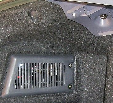
PROBLEM: The HB (HatchBack) of my Hyundai Elantra GT is entirely too dark! The problem becomes even worse if I have a box or two in there that completely block the stock light which is positiond too low and is too dim.
SOLUTION: Add FOUR bright white LEDs to the HB that will illuminate from above. They aren’t the brightest solution, but they are small, take very little power, and I just love LEDs!!!
NOTE: This project was meant to be as non-intrusive as posible so if I wanted to remove everything I could do so without very much evidence that anything had been done. I also replaced the stock bulb in the hatchback with three LEDs (not discussed on this page). Final note: This elantra modification is much nicer than version I because (1) I added two more LEDs, and (2) I put most of the wires behind the liner (inspired by southpawboston’s mod here).MATERIALS:
4 – bright white LED’s: 5mm, 3.6V, 30mA
4 – 5mm LED holders from RadioShack: Item #: 276-079
2 – LM317 IC’s
2 – 39 ohm resistors INSTRUCTIONS:Step 1:
To make things easy I connected to the existing light to provide the power for my new lights. This way it would turn on when the back was open. I tried to solder wires onto the ends of the existing stock bulb (I could have soldered to the socket connectors, but didn’t want to “ruin” them), but the solder wouldn’t stick (stainless steel?). Instead I removed the existing bulb and created my own LED “bulb” which fit snugly into place and also provided access to the power.Step 2:
I positioned the LED’s in the easiest to access areas, and areas where I thought they would provide the best light. I drilled 1/4 inch holes in the plastic liner (see picture) that supports the HB cover and also into the taillight covers. The positions are excellent as they are angled just right, easy to access, up high enough so it doesn’t get blocked, and out of the way. The best part is I didn’t have to really pull anything apart to get to these spots and drill the hole, which I really like! I pushed the LED though the back of the hole, attached the LED holder, and pushed it snugly into place!Step 3:
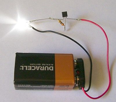
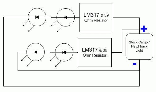
Schematics: In the past I’ve simply used resistors in series with my LEDs, but I notice that the brightness varied when the car was on and off. This is because LED’s are super sensitive to small amounts of changes in voltage. When my car is off I get about 11.5 volts… while it is running I can get up to 13.5 volts… this is a big difference to these little LEDS. Fortunately I discovered the LM317 IC which gives me a constant current of my choosing. I decided to use two strings of two LEDs in series, each with their own LM317. I was shooting for 30 mA at each LED so I used a 39 ohm resistor with each LM317. (Here is a link to using the LM317). Here is the basic LM317 circuit with a white LED running off of a 9v battery. The resistor determines the constant current. In the case below, the 30 ohm resistor determines the current to the LED to be 40 mA.
 Here’s the schematic of what’s in the HB:
Step 4:
Next I wired everything together. I did as much soldering outside of the car as possible and left only a few connections to be soldered inside the car. I fished the wires down from the stock light where I split it and took one set of wires to the right and up to the right taillight. Next I ran the second set accross the bottom and fished it up into the left taillight.
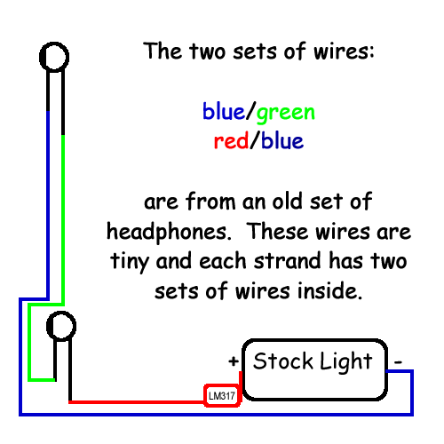
From the taillights I ran small wires (that I got from an old set of headphones) to the upper LED’s. These are the only wires that you’d be able to see. Fortunatley they are black, really tiny and out of the way.
Below is how I wired a single set of LEDs:
Now I have cool lighting in the back of my car exactly where I need it! They aren’t SUPER bright, but at night they’re just perfect!
The Right side with my replacement LED bulb (where the stock bulb was) and two LEDs: one in the blinker cover (middle far-right) one in the molding (middle top).
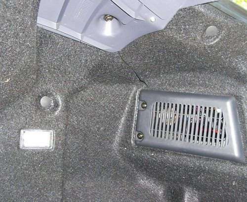
The left side with two LEDs: one in the blinker cover (lower left) one in the molding (upper right).

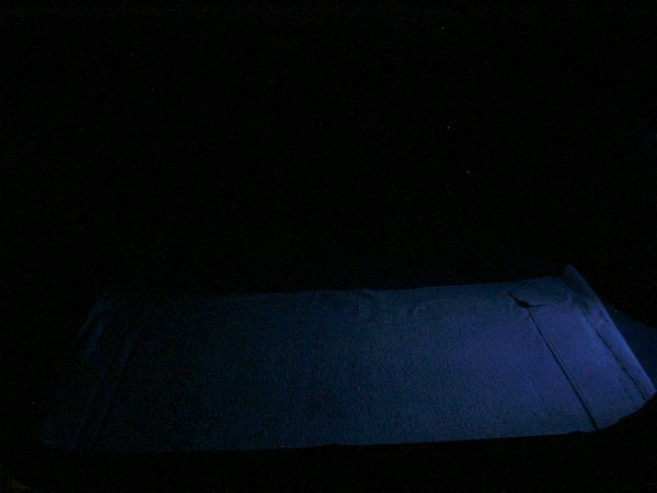
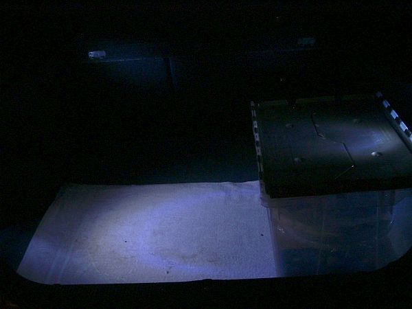
Some pictures at night:
Stock Light Only:

Stock Light Only (modded with LEDs):
Stock Light Only (modded with LEDs) with BOX blocking the light:
With the additional 4 LEDs
With the additional 4 LEDs and with BOX blocking the light:


it is so helpful for new learner,reseacher for me too.so thanks for it and i wish you for more progress and successes.thanks bye.
How did you figure what wattage resistor to use? I have a motorcycle tai light that I have to replace a resistor that burned up so I can’t see the color bands. I figured what ohms value I need but I think i’m running the numbers wrong because I’m coming up with over 3 watts and I know none of the other resistors on the board are that high wattage.